Easy controller manual
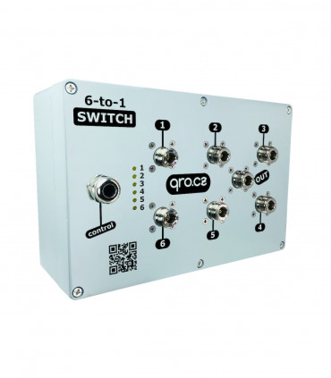
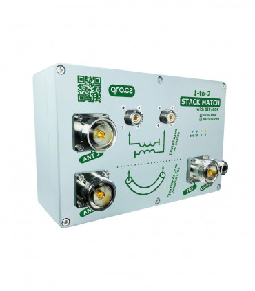
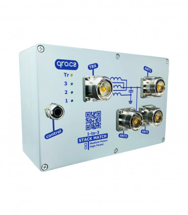
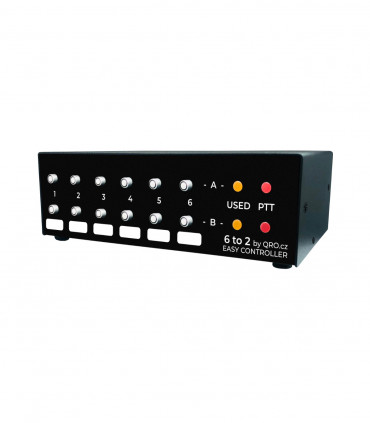
This manual page is for four versions of the easy controllers. Each version has got classic and remote controlled version.
Easy controllers allow you to control:
Jump to
Front panel description
Rear panel description
Parameters
Connection and connectors description
Output driver settings
4-1 Easy Controller Connection
6-1 Easy Controller Connection
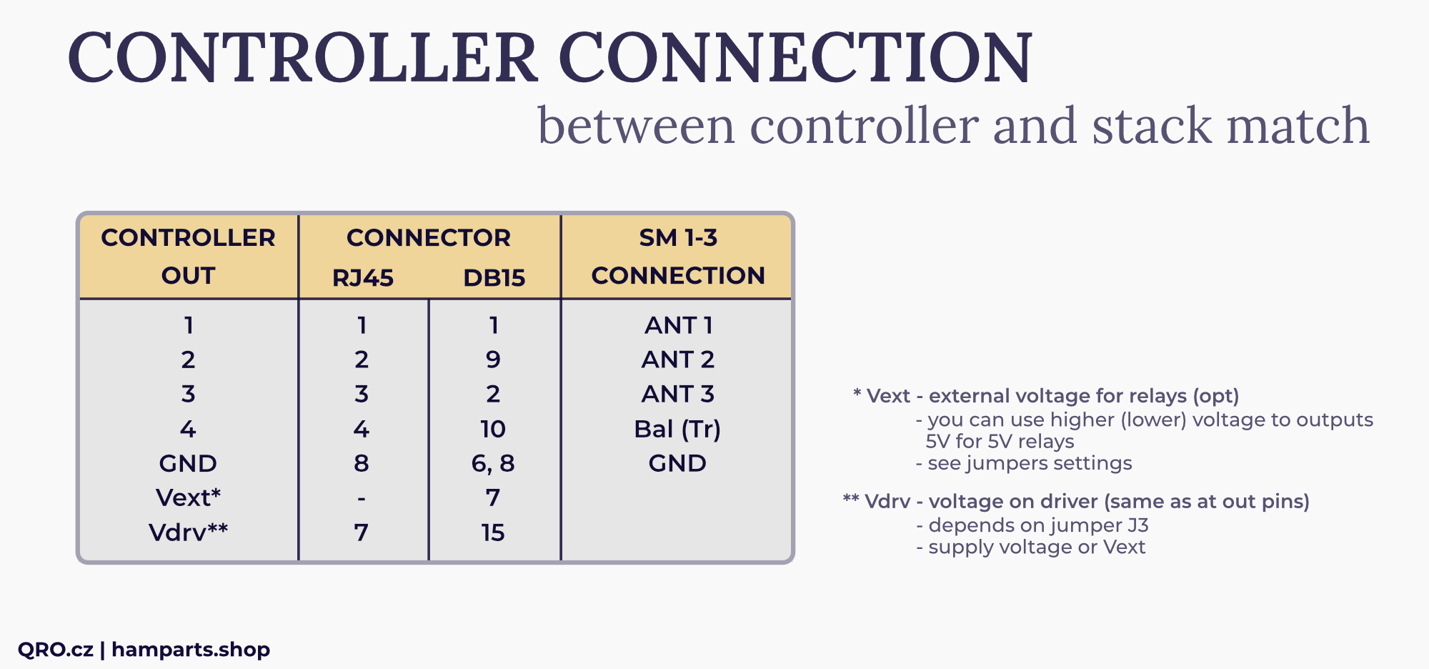
Stack Match 1-2 Easy Controller Connection
Stack Match 1-3 Easy Controller Connection
Stack match configuration
Stack Match 1-2 Easy Controller Connection
Stack Match 1-3 Easy Controller Connection
Remote control
External Remote Relays
QUICK setup
QUICK setup - manual way
Controller IP address
User interface (UI)
IP access to the UI
Configuration page
After configuration page
Product details
Front panel description
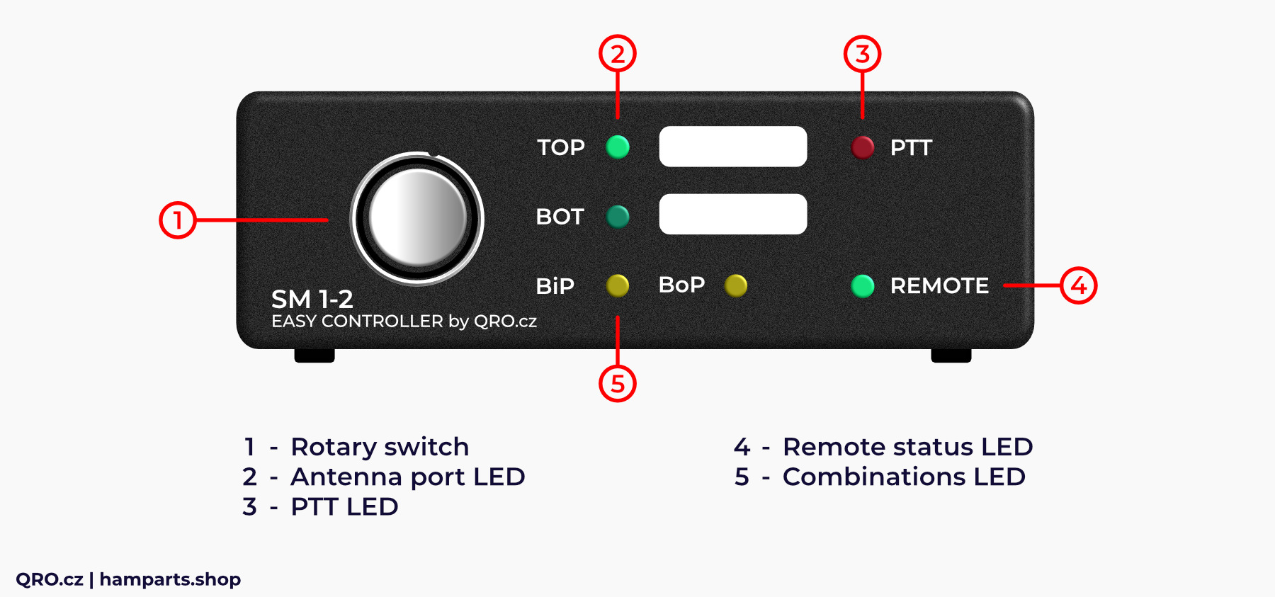
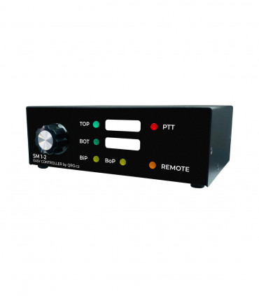
There is front panel example for Easy Controller SM 1-2. It is very similar to the rest Easy Controllers.
1. Rotary switch
- Rotary switch for all combinations
- When the remote control is ON, this switch is disabled
2. Antenna port LED
- Output antenna port indication
3. PTT LED
- PTT LED indication
4. Remote status LED
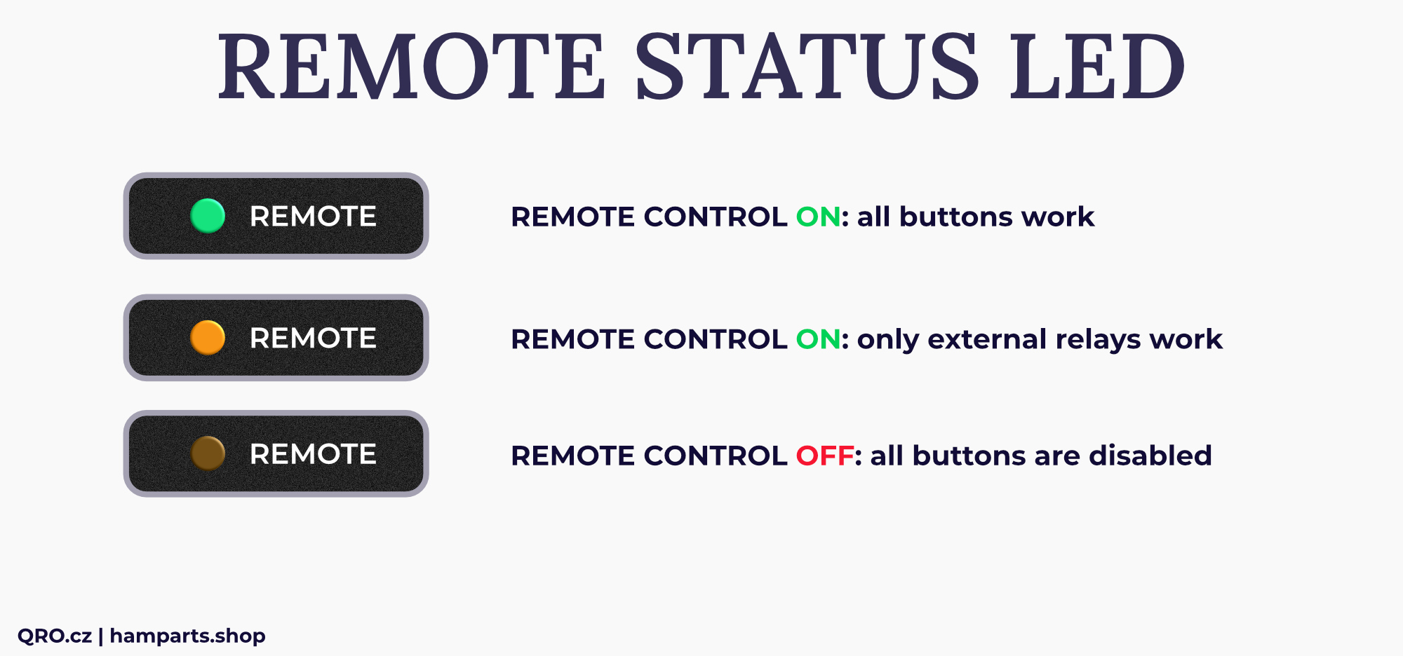
- This is remote control status LED
- When you use remote control then the LED is ON
5. Combinations LED
- LED indication for SM 1-2
- Combinations for Both-In-Phase and Both-Out of-Phase
Rear panel description
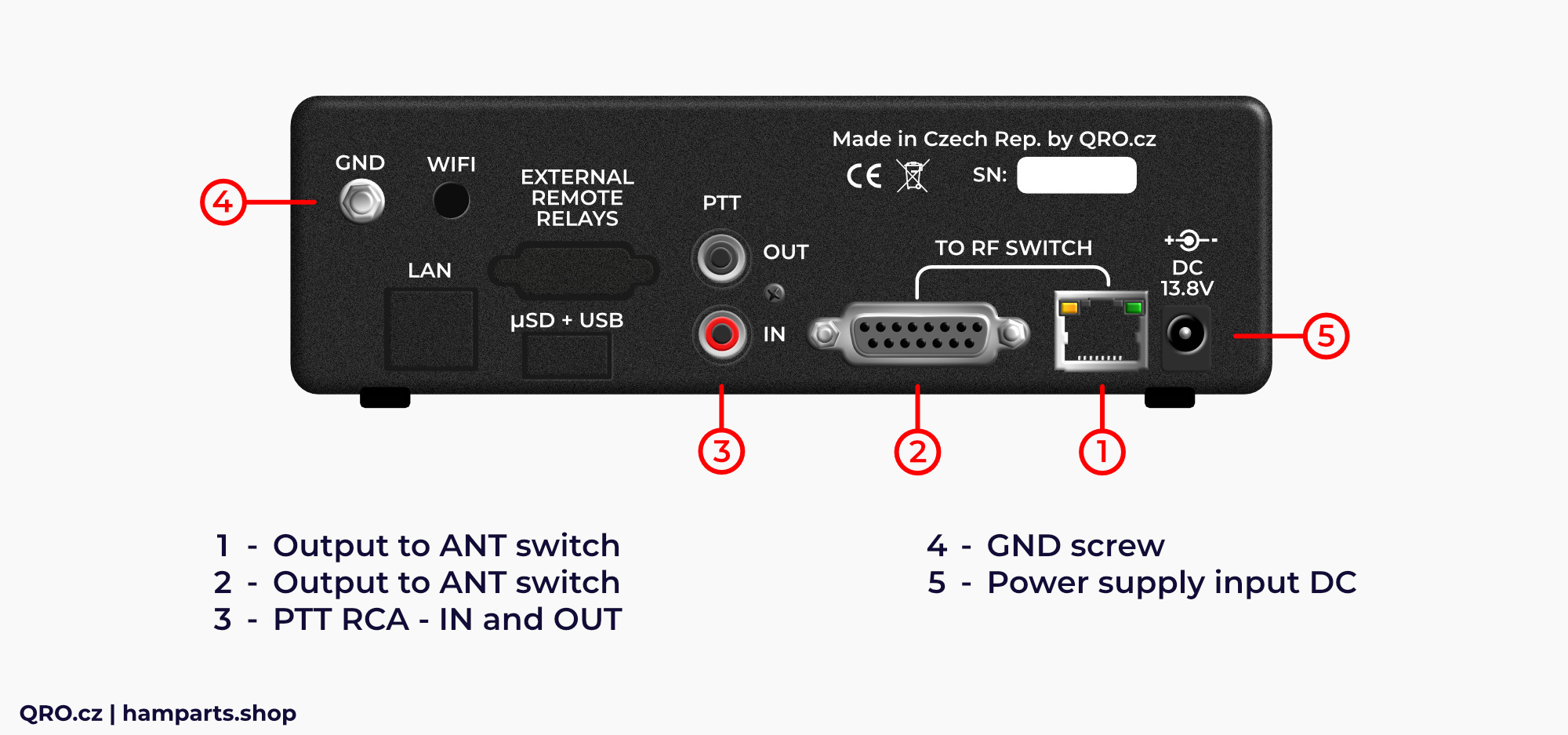
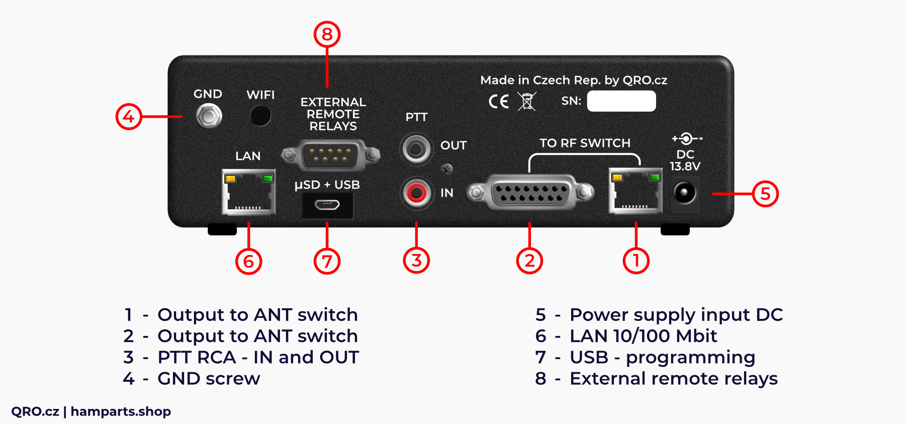
There are two pictures of the rear panel. The second one has got Remote Control IP module.
1. Output to ANT switch
- Output to the antenna switch or stack match
- This is NOT LAN port!
2. Output to ANT switch
- Output to the antenna switch or stack match
- Similar to 1. but there are some more pins - see manual
3. PTT RCA
- PTT IN and OUT
- Works in sniffer mode (listening for the PTT signal without any effect on it) PTT IN is directly connected to PTT out or with output FET switch - see manual
4. GND screw
- There are high voltage protections - to work right, please, connect GND to the common ground point
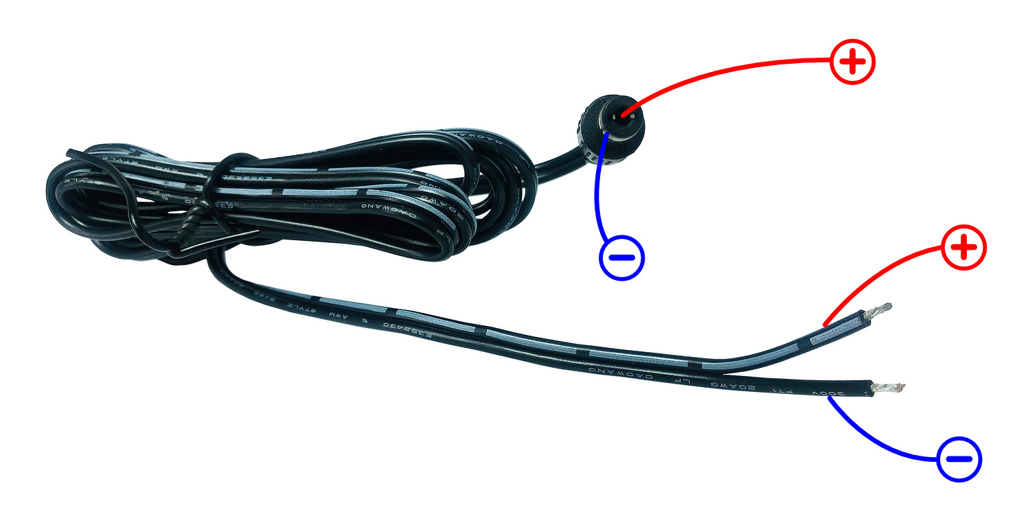
5. Power supply input DC
- DC input connector
6. LAN 10/100 Mbit
- Remote Control IP module LAN port 10/100 Mbit FD (Full Duplex)
- With high voltage protections and common-mode filter
7. USB
- USB connector for code upload
8. External remote relays
- External relays for custom use from the remote UI web page
- Could be configured as + voltage or for switching to ground - see manual
Parameters
- Input DC voltage: 12 - 14 V
- Input current: DC less than 1 A
- PTT IN: compatible with 5V PTT logic
- PTT OUT: PTT IN connected to PTT OUT or PTT out with FET switch 0.5A
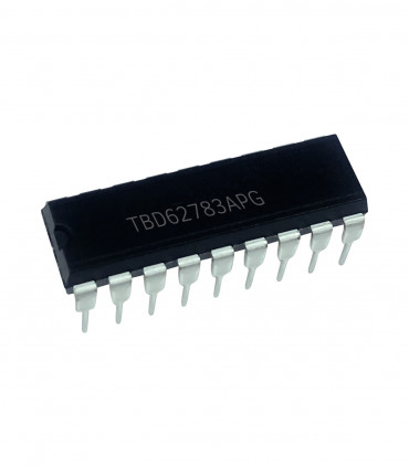
- TBD driver is included
- Output voltage: DC from input or Vext minus 0.7 V
- Output current: max. 500 mA DC per pin and together for all pins
- Remote LAN: 10/100 Mbit FD with protections and Common-mode filter
- External relays: positive or ground switching
- External relays current: max. 500 mA DC per pin and together for all pins
- Remote control: web based and WS (WebSocket), can be part of centralized system
- EXT voltage for drivers: max. 26 V DC (at DB15 and DB9 connector)
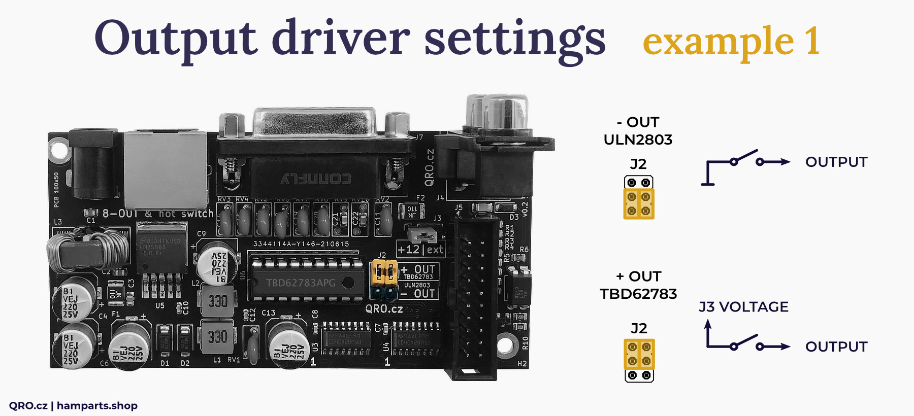
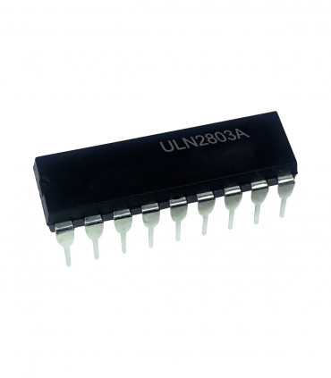
⚠ IMPORTANT NOTE: Default output setting is with TBD driver. Output control is +12V. If you need to control external devices by switching to ground, you must replace the driver with ULN and change the Jumper settings. ULN driver is NOT included. You can buy it here.
Connection and connectors description
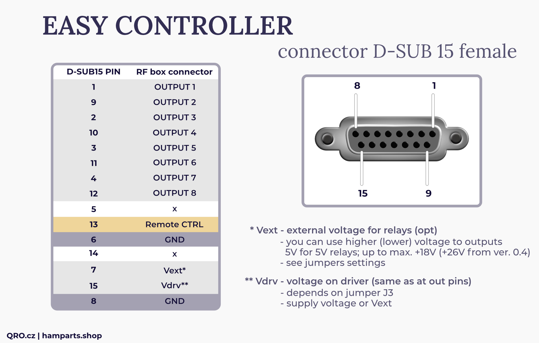
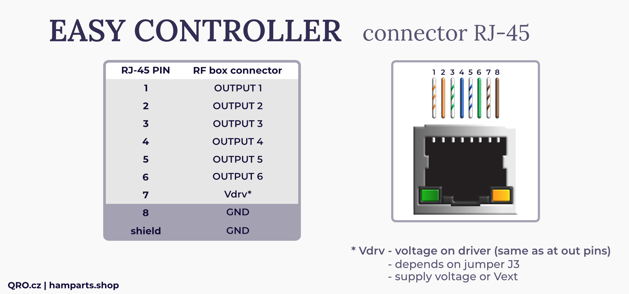
There are two output connectors where you can connect antenna switch or stack match. Both are almost the same. You can buy RJ45 LAN cable all over the World, what is big advantage. DB15 has got possibility to apply external supply voltage - in the case you use relays with different voltage from 12V DC.
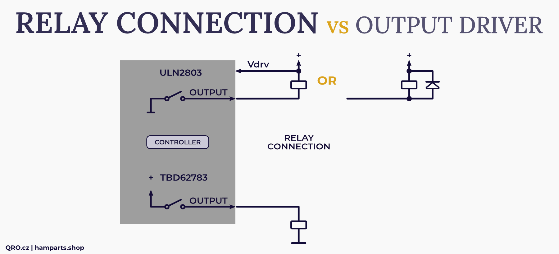
Controller also allows to use positive DC voltage out or switching outputs to ground. Our switches and stack matches need +12V to switch port on. If you have your own with switching relays to ground, you have to change internal driver and set jumpers to right position. You can find more info in this manual.
OUTPUTS - outputs pins to switch or stack match. Could be +12V or to ground - depends on driver inside.
REMOTE CTRL - only outputs information pin with +5V when Remote Control is ON
Vext - External voltage input. You can use this when you use relays with different voltage from +12V.
Vdrv - voltage at driver. Connect it to the supply voltage of relays when you use switching to ground driver - this enables internal protection diodes.
OUTPUTS - output pins to switch or stack match. Could be +12V or to ground - depends on driver inside.
Vext - External voltage input. You can use this when you use relays with different voltage from +12V.
Output driver settings
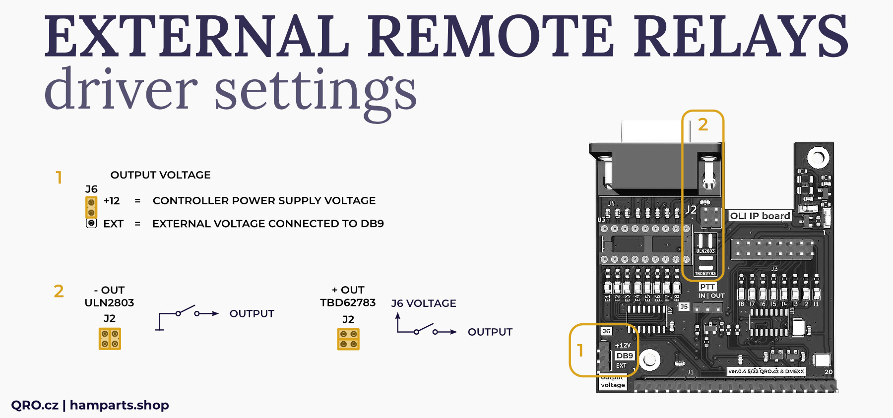
⚠ IMPORTANT NOTE: PLEASE, before you change the settings, you need to change the output driver and jumper settings. This can only be changed when the controller is switched off. Never turn on the controller when you have the opposite jumper and output driver settings.
Output pins to switch or stack match. Could be +12V or to ground - depends on driver inside.
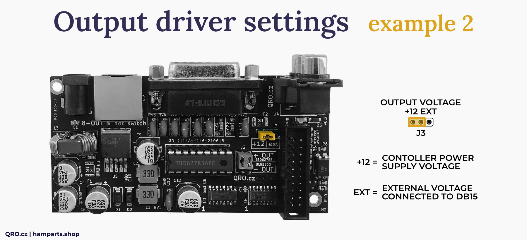
External voltage input. You can use this when you use relays with different voltage from +12V.
Depends on the device you would like to control, you can use drivers with + voltage output or switching to the ground. You have to change driver IC and do right Jumper settings. Maximal output voltage is + 26 V DC and 500mA current per pin and total for all pins.
+12 = In this position the driver has got voltage from the power supply connected to the controller.
EXT = In this position the driver has got voltage from the external power supply, connected to the DB15 connector - see manual. Maximal EXT voltage is +26 V DC.
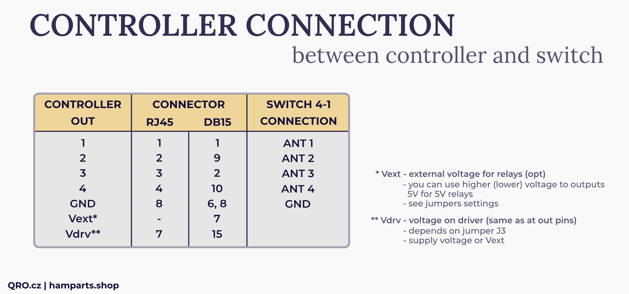
4-1 Easy Controller Connection
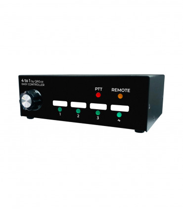
- You need 5 wires to connect 4 port antenna switch. Four wires for control voltage + ground.
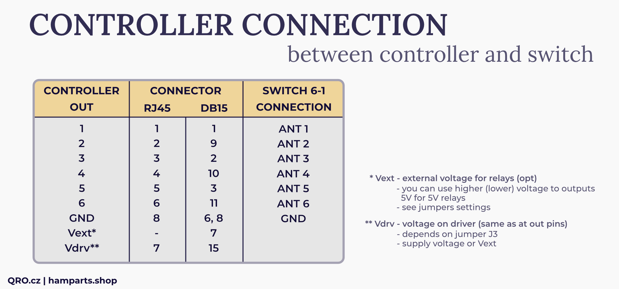
6-1 Easy Controller Connection
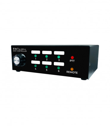
- You need 7 wires to connect 6 port antenna switch. Six wires for control voltage + ground.
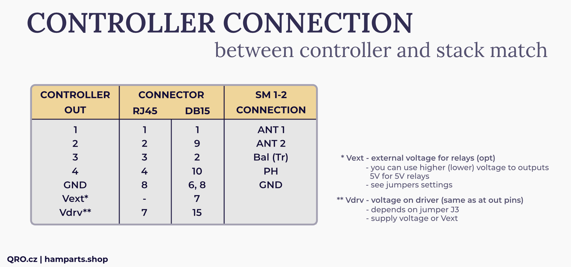
Stack Match 1-2 Easy Controller Connection
- You need 5 wires to connect stack match. Four wires for control voltage + ground.
Stack Match 1-3 Easy Controller Connection
- You need 5 wires to connect stack match. Four wires for control voltage + ground.
Stack Match configuration
Both Stack Match Easy Controllers allow to control any stack match with up to 4 control wires. There are many different stack matches at the market, with very different switching matrix tables.
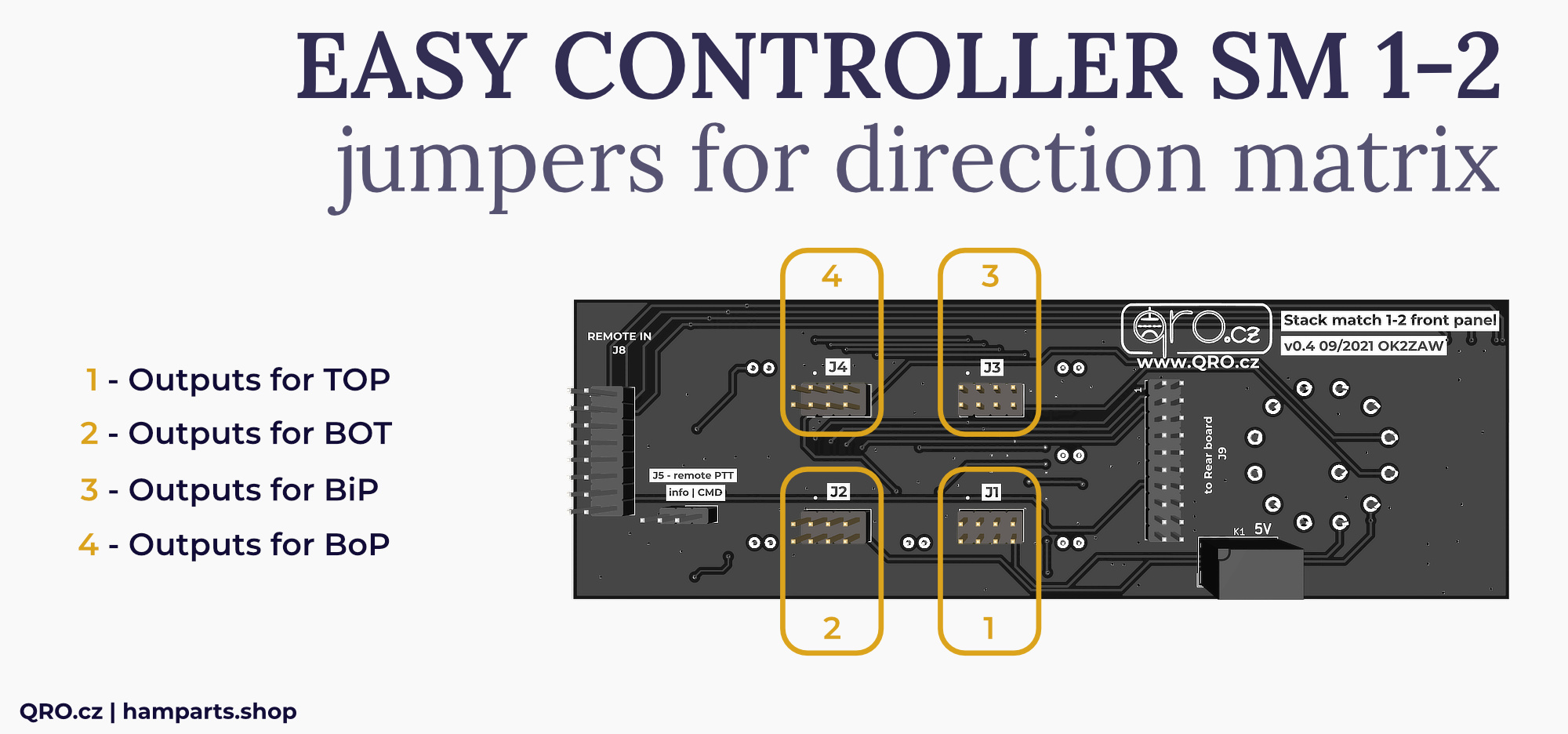
By the jumpers at to front panel you can set matrix table as you like - for up to 4 outputs wires.
Stack Match 1-2 Easy Controller
Controller is pre-configured for our Stack Match 1-2. There are four groups of the jumpers. Each group is one switch position.
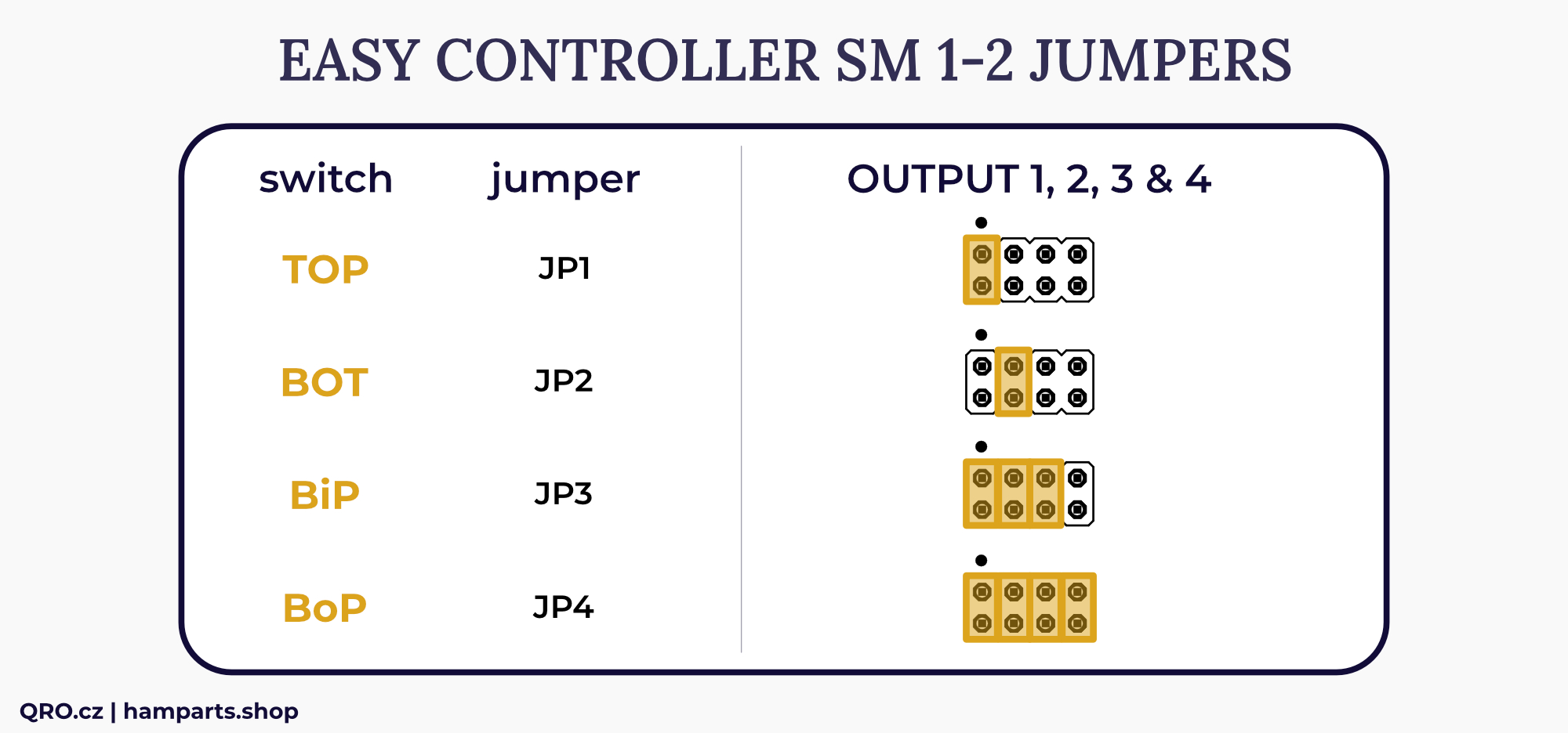
Jumpers settings for our Stack Match 1-2
- Position one is TOP antenna - output 1
- Position two is BOT antenna - output 2
- Third position is BiP (Both antennas In Phase) - output 1+2+3 (3 is matching transformer)
- Position Four adds also Phase Transformer into BoP (both antennas Out of Phase) - all outputs are active
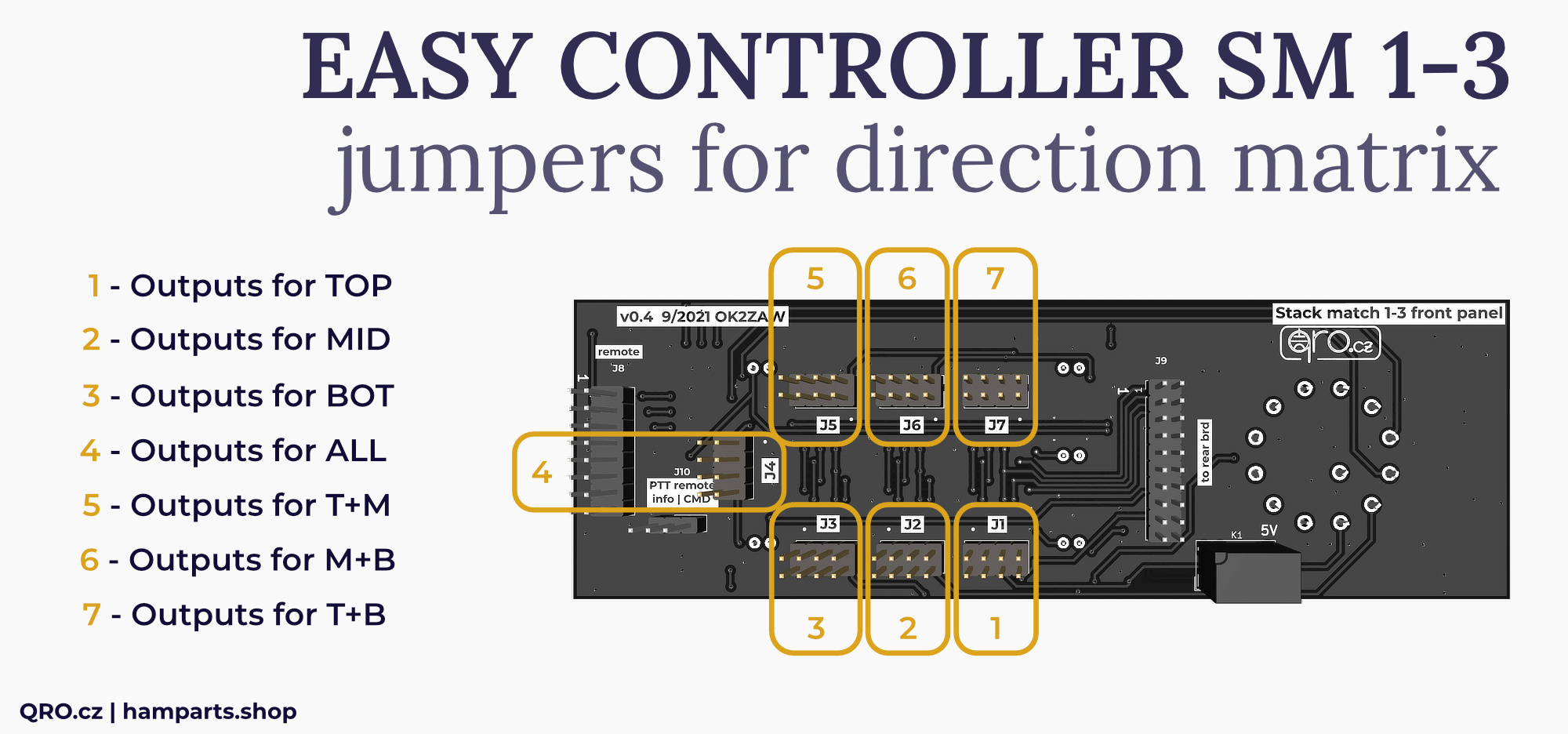
Stack Match 1-3 Easy Controller
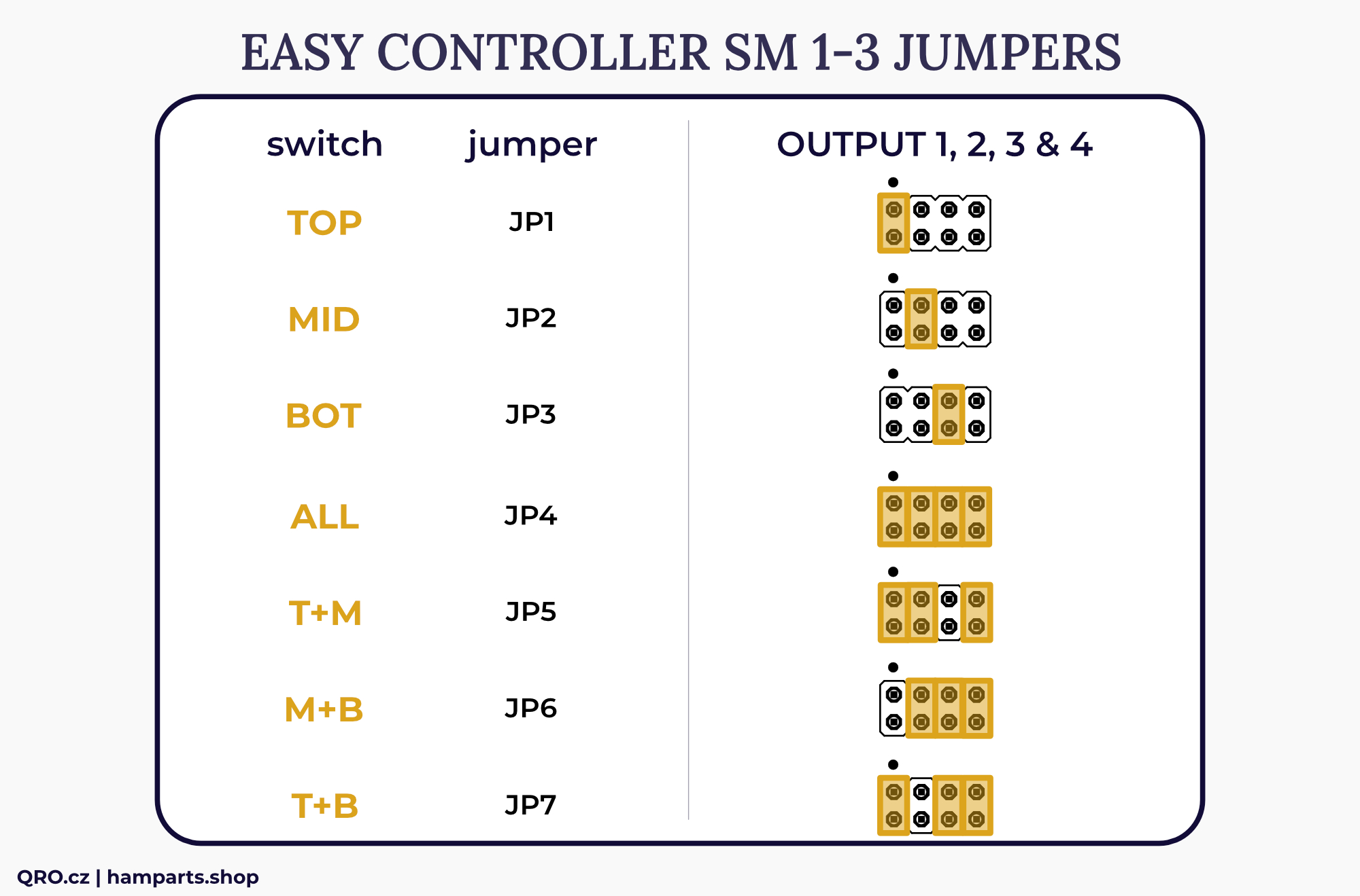
Controller is pre-configured for our Stack Match 1-to-3. there are seven groups of the jumpers. Each group in one switch position.
Jumpers settings for our Stack Match 1-3
Remote Control
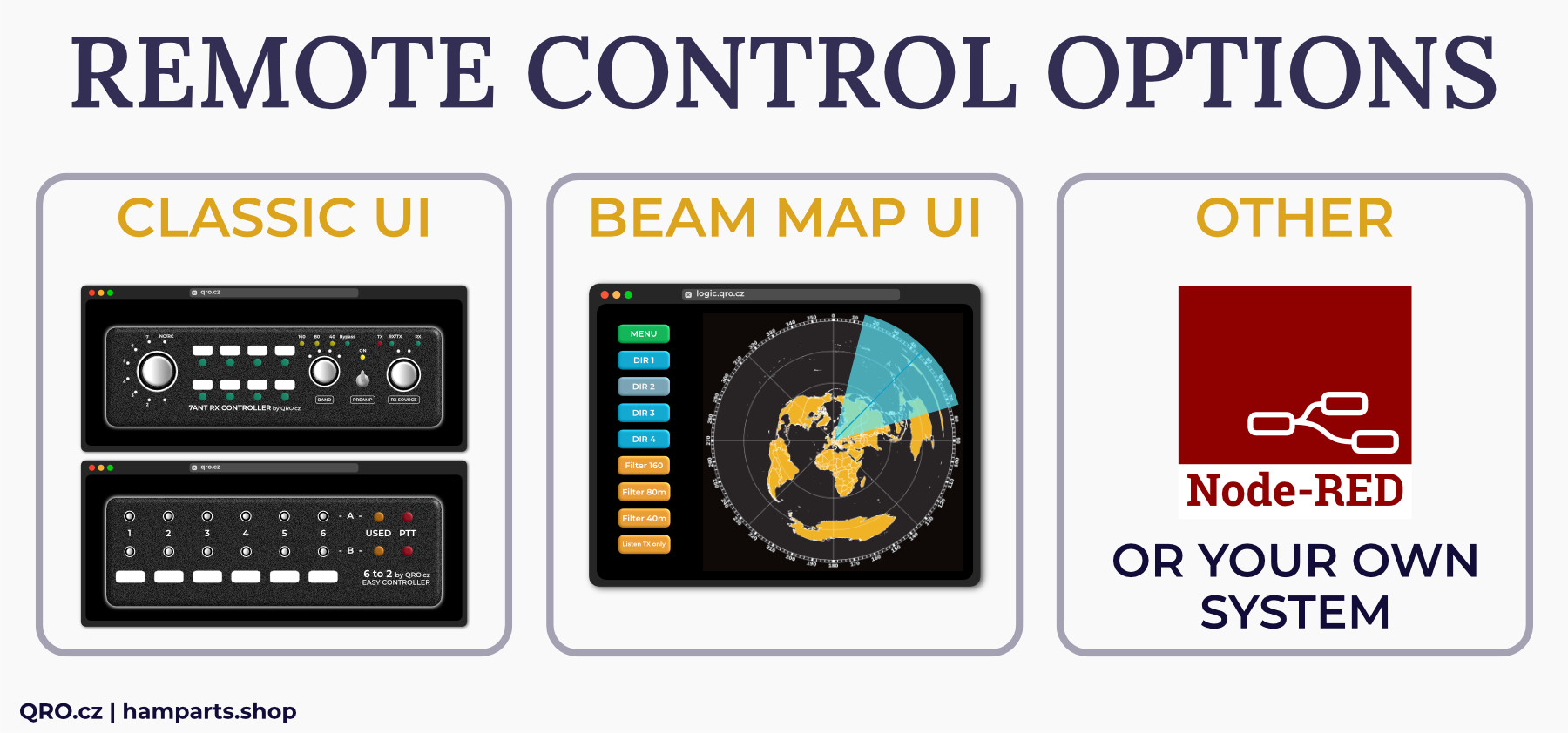
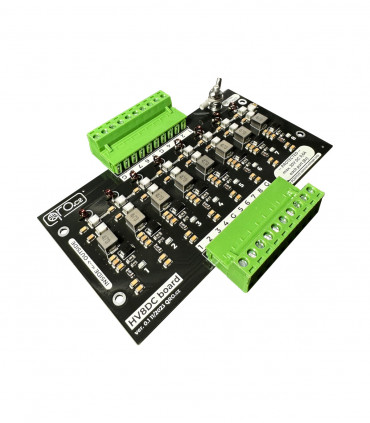
There is WEB IP module and External relay daughter board. These PCBs can be added also into classic controller version. Remote control is based on web page with User Interface (UI) looking like front panel of the Easy Controller. If you want to know more about REMOTE SYSTEM, please read our technical articles.
External Remote Relays
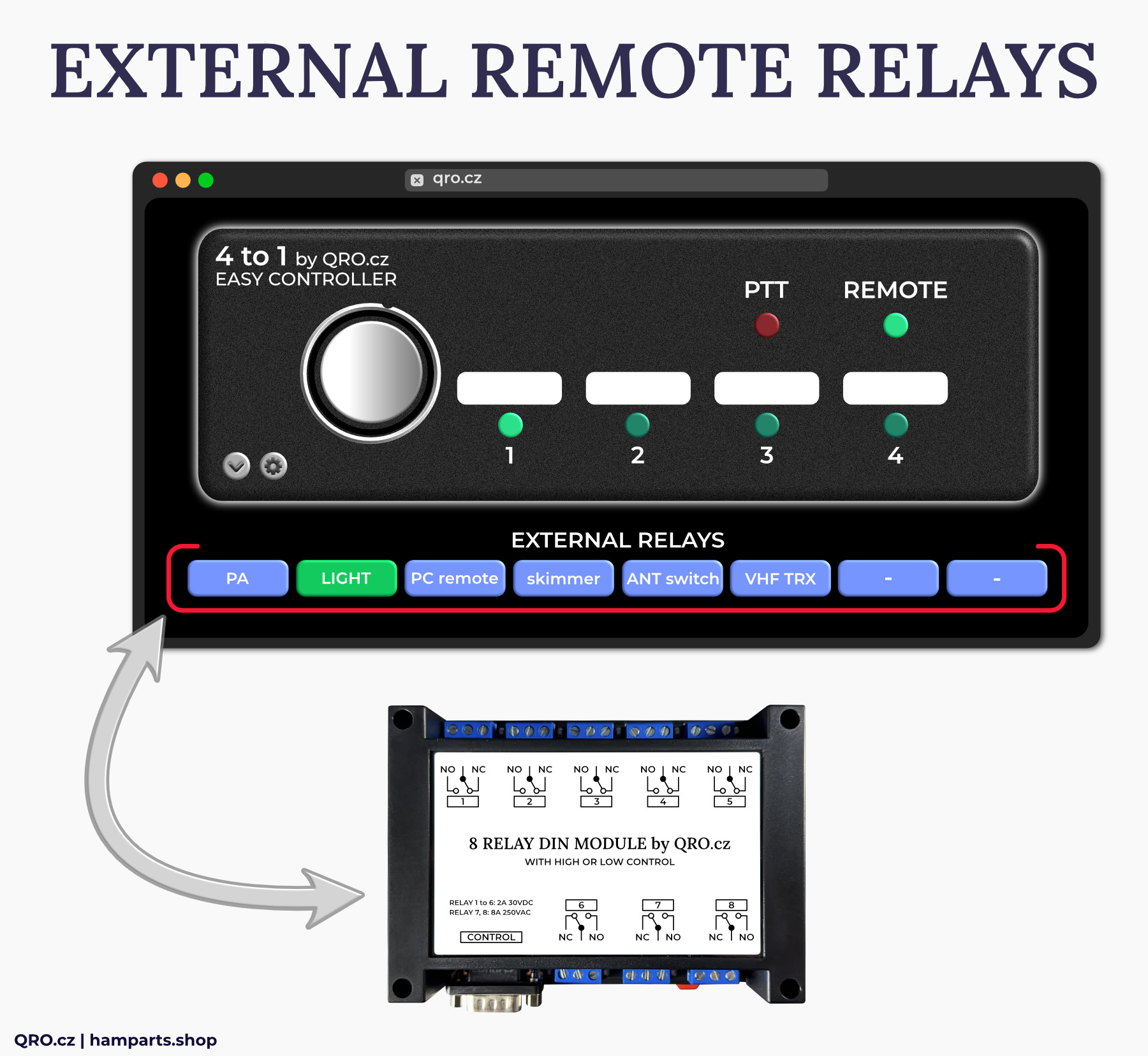
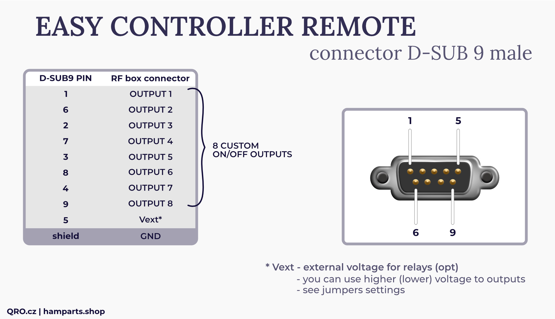
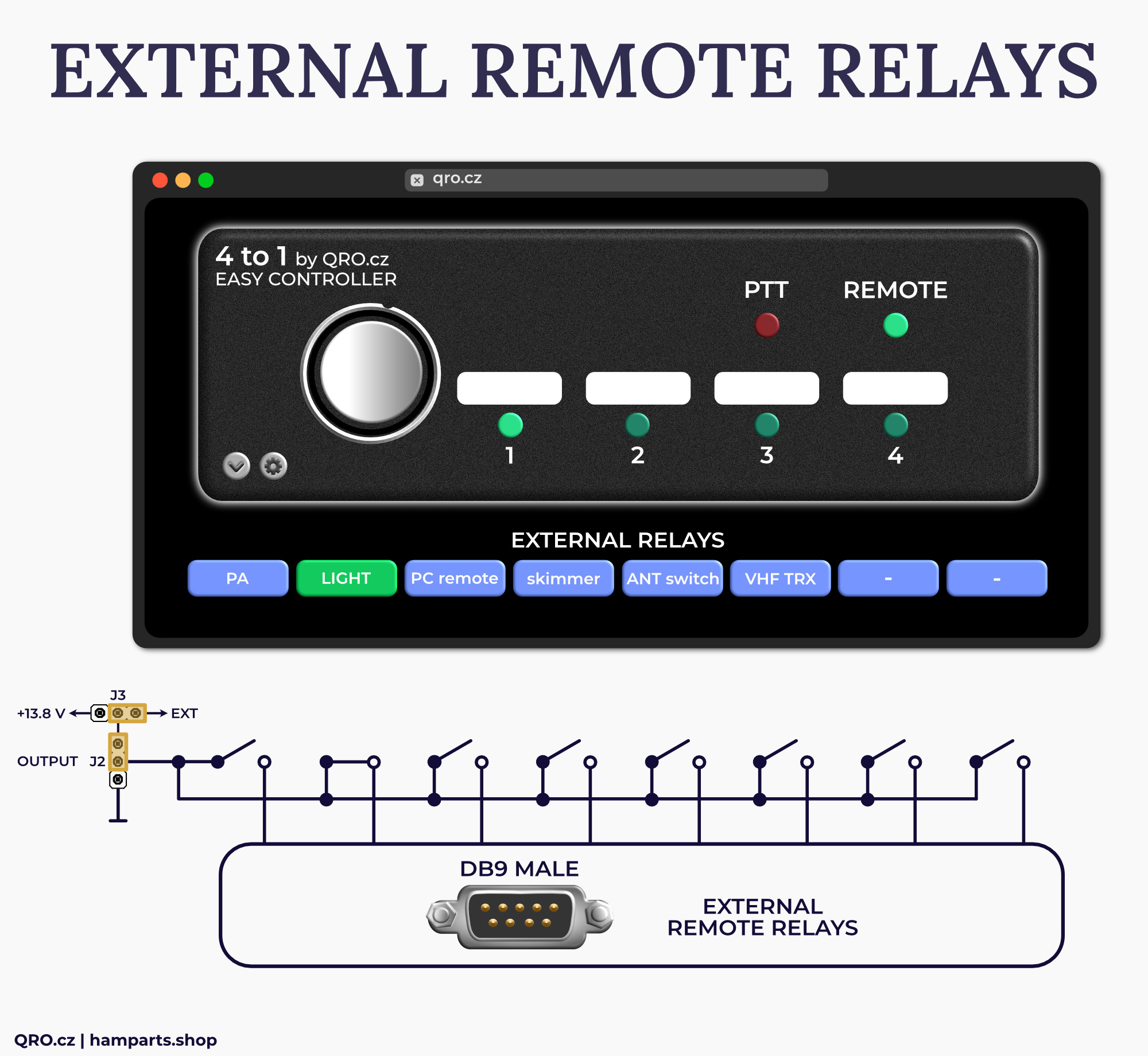
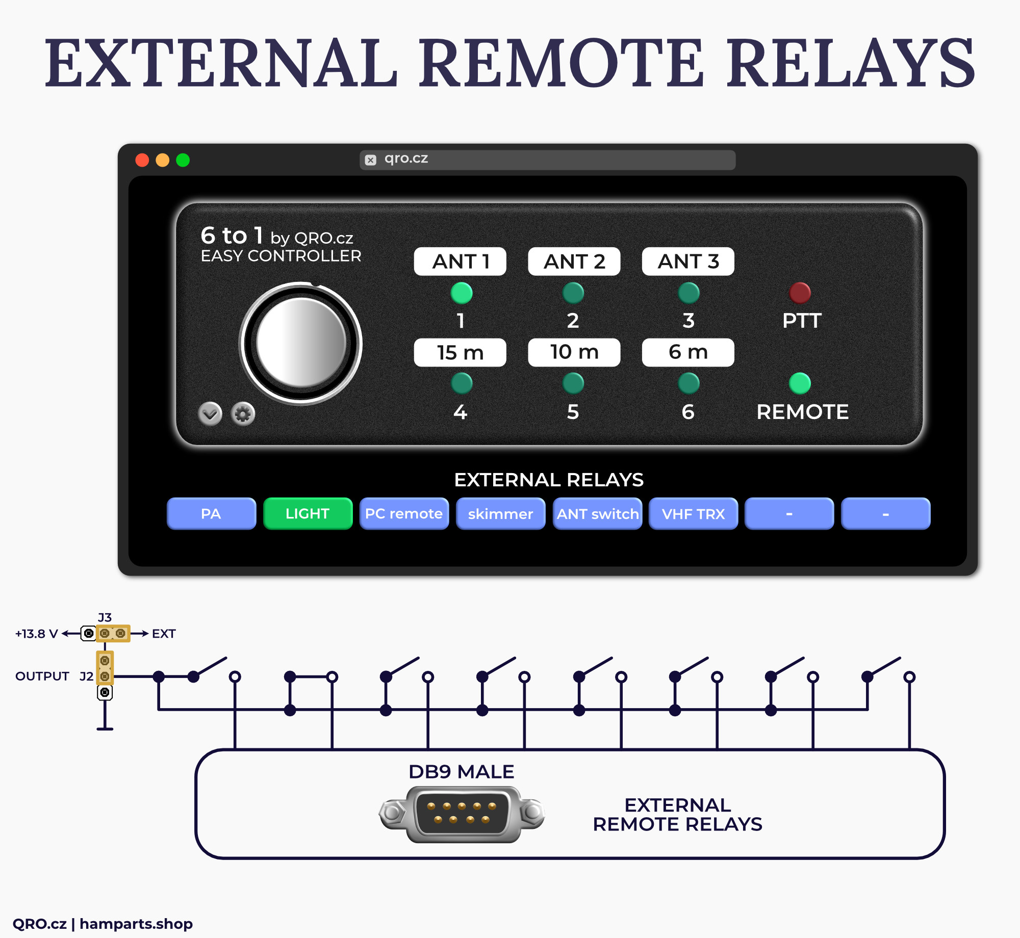
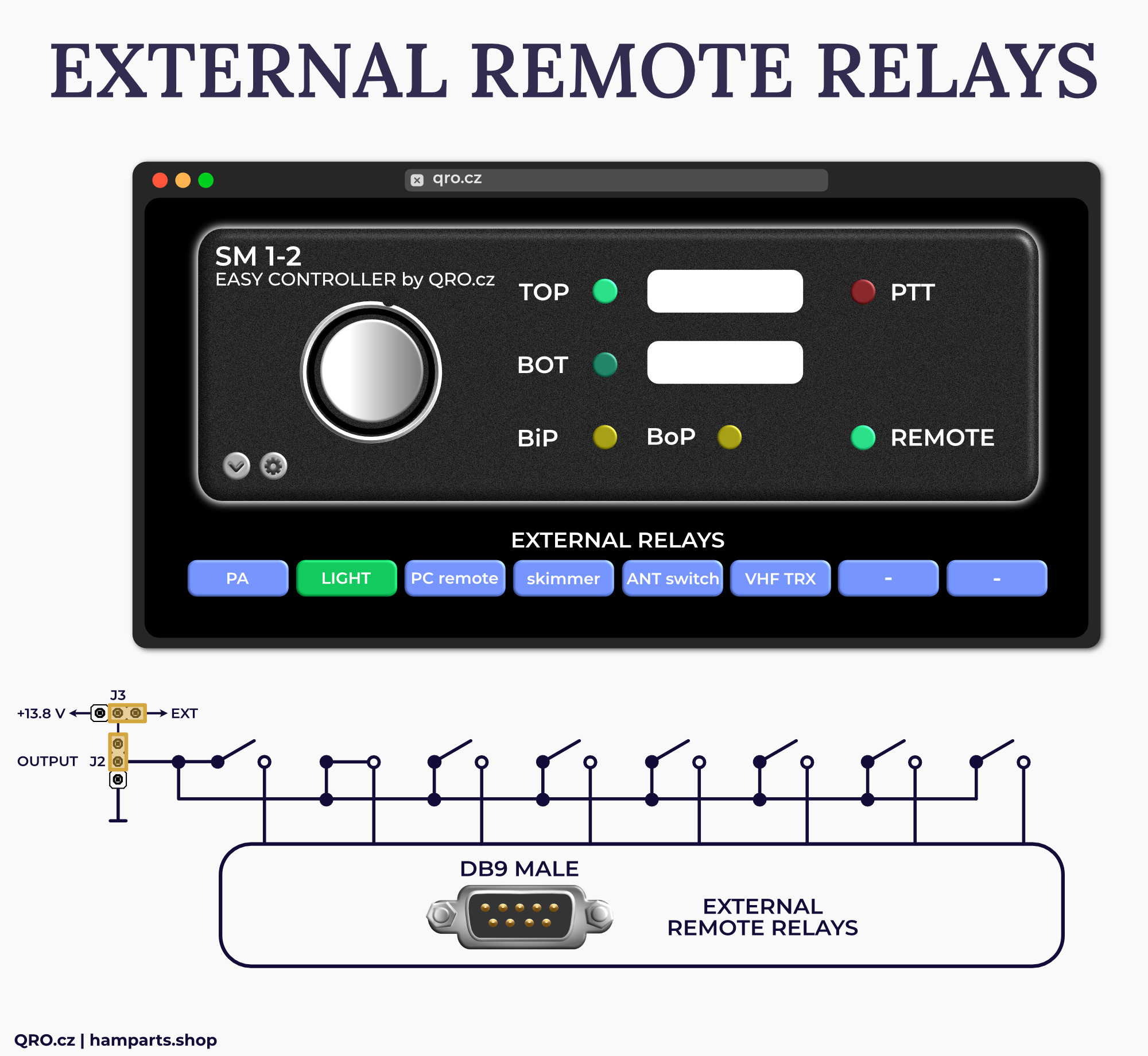
There are another 8 external outputs. These outputs can be used for any custom ON/OFF switching. Default configuration is with positive output voltage when the output pin is ON. Could be changed to switching to ground. You have to change Driver IC and set right jumper configuration. This second driver IC is NOT included in the package.
 |
 |
|---|---|
 |
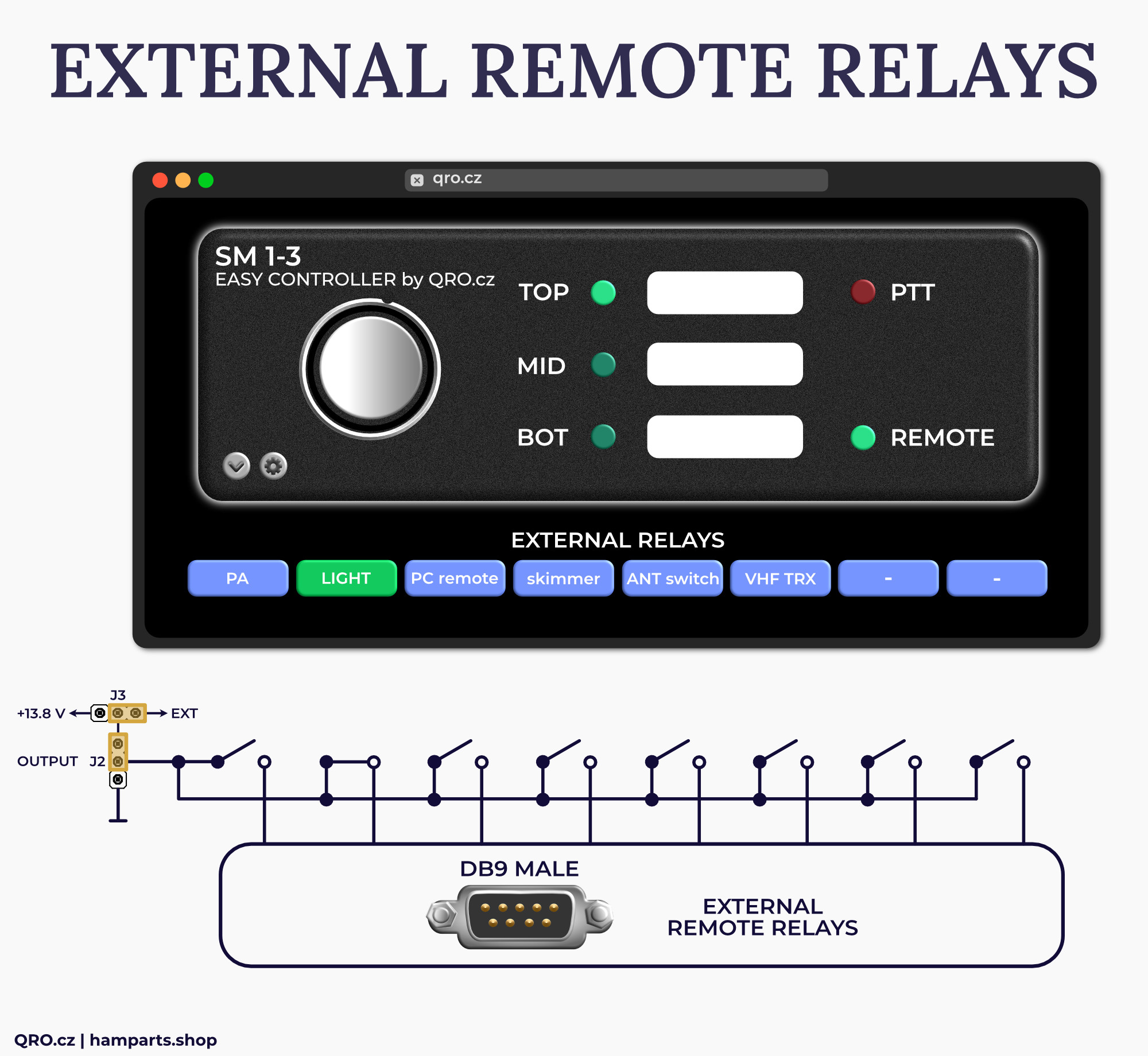 |
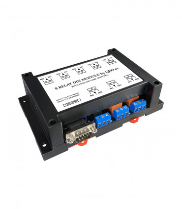
example with 8 Relay DIN module
OUTPUTS - output pins to switch or stack match. Could be +12V or to ground - depends on driver inside.
Vext - External voltage input. You can use this when you use relays with different voltage from +12V.
There is a daughter board of the remote control unit with the settings for the external remote relays.
There can be also both drivers for the external remote control relays. By default, there is TBD IC with + 12V output. ULN driver IC is NOT included in package. You can use external DC voltage up to 26 V - depends on J6 jumper setting.
QUICK setup
Mike DM5XX has prepared Entry Point and Easy Assistant pages. This is the best way to go, see all possibilities of our UIs.
Please, start with ENTRY POINT manual page
QUICK UI setup link is there: EASY ASSIST
Please, follow our YouTube channel
⚠ IMPORTANT NOTE: We recommend a VPN while using remote access from outside your network in general.
QUICK setup manual way
1. Find IP address of the controller in your LAN
2. Open link in your web browser (select right one by the controller version
- 4-1 controller: http://logic.qro.cz/logic/EasyControl/index4to1.html
- 6-1 controller: http://logic.qro.cz/logic/EasyControl/index6to1.html
- SM 1-2 controller: http://logic.qro.cz/logic/EasyControl/index1_2.html
- SM 1-3 controller: http://logic.qro.cz/logic/EasyControl/index1_3.html
3. You should see web UI. Please, close warning with Websocket error (you have to set right IP address)
4. Open config and fill in your controller's IP address
5. Press update
6. You can update all you need as ANT name, font size etc. Again, press update button
7. Go to bottom of the page and press Generate link
8. Press Open from link - you will have new window with updated parameters which should work and you can control the controller
9. Save this link somewhere - you can use it from any device in LAN
10. Good to know
- Take care that your link starts with "http://" (not https! Some Browsers like Chrome add this automatically)
- If you changed something on the config page, please always press "update" on that Field. Create link after you completed everything
- Always use VPN. Never use and trust Portforwarding. Please see:
https://uk.pcmag.com/vpn/93737/how-to-set-up-and-use-a-vpn or
https://www.hellotech.com/guide/for/how-to-port-forward
- Ask a friend who has knowledge of setting up VPN (or Portforwarding). Since this is specific to your router or internet setup, we cannot help you there a lot.
Controller IP address
This controller is configured as DHCP client - looking for IP address from DHCP server (usually your home internet router).
At first, you have to find IP address of your device. There are more ways how to do it:
1. Find IP in your router:
- log in to your router and look at DHCP leases table (Host Name should be Impero)
2. IP addresses scanner software:
- use any IP address scanner software, for example Advanced Port Scanner
There you should be able to find IP address with Port 59 - this is your device
User interface (UI)
All the logic is done in UI. You do not need to upgrade code in your controller
1. Remote control knob
- The big knob switches remote control ON and OFF
- Press it once: REMOTE LED is GREEN = all UI buttons work
- Pressing again: REMOTE LED is ORANGE = main buttons (antenna) are locked, external relays work
- Pressing again: REMOTE LED is DARK = buttons are locked
2. PTT status LED
- This is PTT status LED
- There is some delay
3. Remote status LED
- Show status of Remote Control
4. Quick control buttons
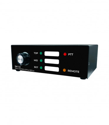
- All combination for Stack Match 1-2 and 1-3 (the example shown is Stack Match 1-3)
5. External relays
- By pressing this button you can hide/reveal External Relay buttons
6. Settings
- By pressing this button you can hide/reveal settings
7. Control LED
- This is the status LED for the communication between UI and controller. After any switching or change in UI, you have to see short LED blinking. If not, please refresh page by CTRL+F5 and check right IP and port settings.
8. External relays buttons
- There are custom ON/OFF outputs. Could be configured as ON = +12V or ON = short to GND
⚠ IMPORTANT NOTE: 8 EXTERNAL RELAYS work even you have antenna ports controlled manually. This means, you can control remotely only these relays and antenna ports could be controlled locally - directly by the knob at the controller.
⚠ IMPORTANT NOTE: Buttons are locked when the PTT is in TX mode. PTT LED follows input PTT signal and there are two PTT hot switch protections! The first one is done at HW side as output latch - you can switch antennas from front panel but when PTT is in TX, output voltage will change when you go to RX again. And UI is locked and does not allow you to switch anything.
How to use User Interface (UI):
Read more in Quick Setup
OLD WAY:
1. Use UI files from our server
These files are automatically updated and you do not need to do anything at your side. There are all files at our server and it all is upgraded if needed.
Server address: http://logic.qro.cz/logic/EasyControl/
There you can find the links to the UI depend on your controller:
- 4 to 1 controller: http://logic.qro.cz/logic/EasyControl/index4to1.html
- 6 to 1 controller: http://logic.qro.cz/logic/EasyControl/index6to1.html
- SM 1-2 controller: http://logic.qro.cz/logic/EasyControl/index1_2.html
- SM 1-3 controller: http://logic.qro.cz/logic/EasyControl/index1_3.html
Full link follows with the IP address: ?ip=192.168.99.54:59
Example for 4 to 1 controller:
http://logic.qro.cz/logic/EasyControl/index4to1.html?ip=192.168.99.54:59
⚠ IMPORTANT NOTE: do not use HTTPS, if the link goes to https, please remove it to http only.
2. Use UI files at your own web server
This could be done for some security reasons.
IP access to the UI
There are more ways to access to the UI web page.
1. Only LAN network
When you are only in your local LAN network - controller and devices which control it - then you can use only your local IP address which you have find before (like 192.168.99.54:59 etc.).
2. Controller in local network - access from internet
The controller is in local network and you would like to access to it from internet.
Not secure way is Port Forwarding done in your router. You have to have Public IP address on it! Please, have a look at your router manual and set port forwarding. You have to set: public port at your public IP address to local IP address and local port (like 192.168.99.54 port 59 in our example).
3. VPN
Security way is VPN - this is question of your router and another home network/PC/tablet/mobile phone. Secured VPN is highly recommended for most access to your local network.
Configuration page
This is configuration web page where you can set ID, IP address, Labels and port parameters.
- URL of device: IP_address:port, example: 192.168.99.54:59
- Controller Labels: Labels for antenna ports
- Offset: Setting offset of Labels - you can center it as you like
- External Labels: Labels for the external remote relays buttons
After configuration page
1. Click at the button: Generate Link
- This link you can use for any web browsers in the same network (VPN)
2. Click at the button: Open from link
- This will open new web browser window with the last configuration
- It is recommended to press Ctrl + F5 to refresh everything to the last changes
- Check small status LED at UI web - must blink when you press any button at UI
Generated link includes IP address and port of the controller in your local network (LAN). You are able to access into it only from the same network, routed network or VPN. When you use Port Forwarding at your router - you have to use your router's public IP and port you set for forwarding. When you are back in your LAN, please use local IP settings.

