HV8DC manual
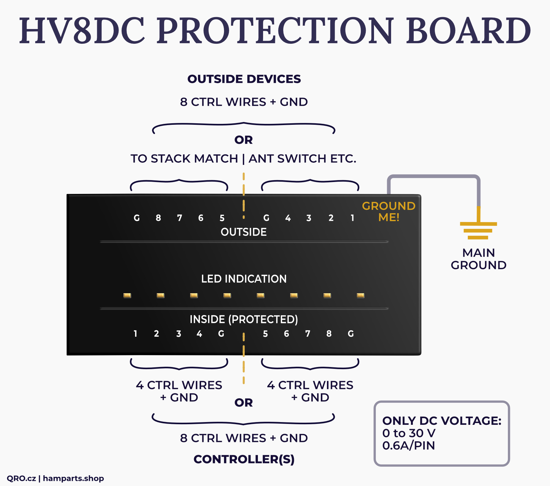
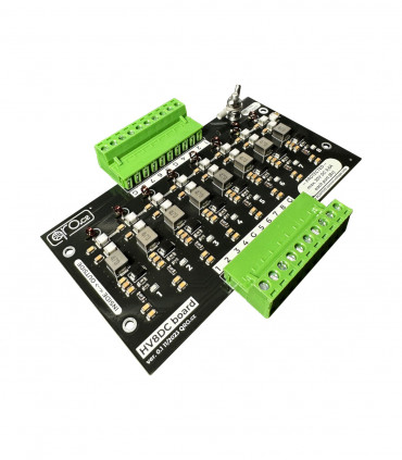
This is a specially designed board to protect up to 8 DC control wires. The connection between the control box and the equipment outside (on the mast) can be dangerous. During a storm, a potential difference can easily arise or voltage can be induced on the control wires - this voltage needs to be safely routed to a common ground potential to protect the equipment behind the protection.
Jump to
Applications
Parameters
Product details
Applications
Functional description:
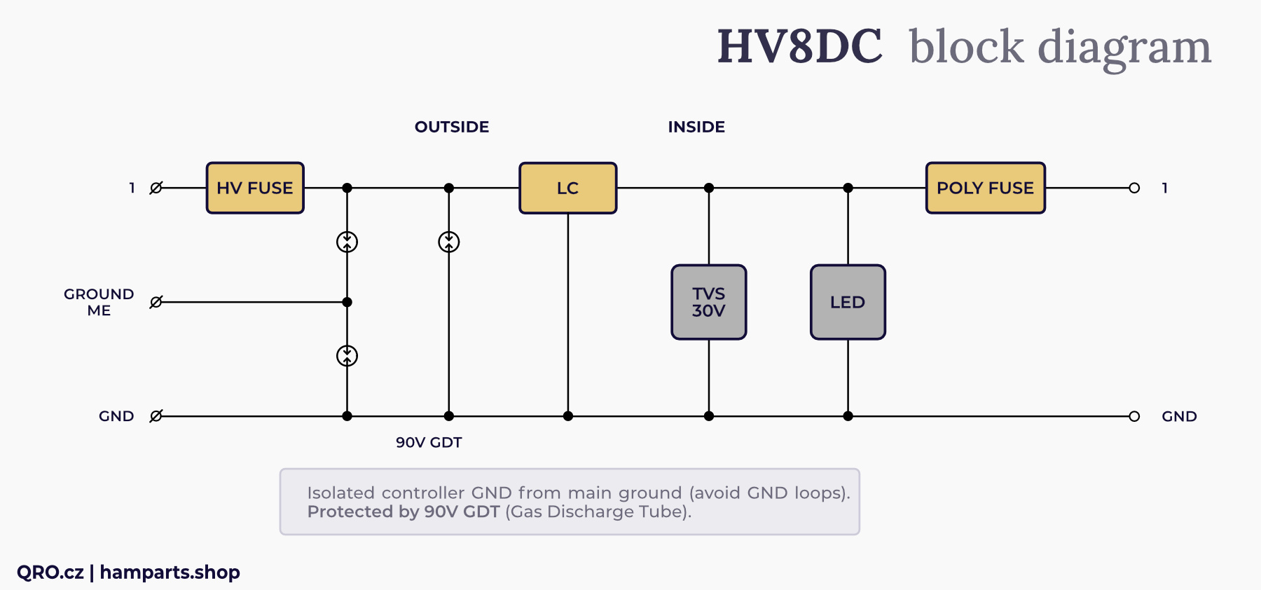
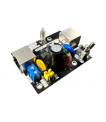
The wire from the external environment comes to the terminal and is fed to the high voltage bridge - a thin wire in the function of a fuse. From there it is connected via a capacitor and GDT (75V) to the GND screw. It then goes to the low pass filter and GDT (75V), where it already shares a common GND with the GND terminal on the connector. The low pass filter consists of capacitors and embedded inductance. Behind the LPF is a DC transil with a clamping voltage of about 40V DC, in the opposite way it works as a diode. In parallel with the transil is an LED indicating the voltage on the pin. The input terminal is connected in series with a reset fuse.
⚠ CAUTION, IMPORTANT! This board is unlikely to protect your equipment from being destroyed by a direct lightning strike. Minimising the effects of lightning is a more complex problem and requires a more comprehensive approach.
This board is designed to provide surge suppression and additional protection for indoor equipment. If more energy is discharged, this board may be damaged - shorting out the protection element.
⚠ NOTE! For proper operation of the protectors, the grounding screw must be connected to a quality grounding point. The connection must be made with the shortest and thickest wire as possible.
The board contains 8 independent wires for DC control - e.g. to connect the control box and antenna switch, stack match etc. There is also a GND wire - connecting the control box to the outside of the box and a GND screw (Ground ME) to bring the overvoltage to the common ground potential.
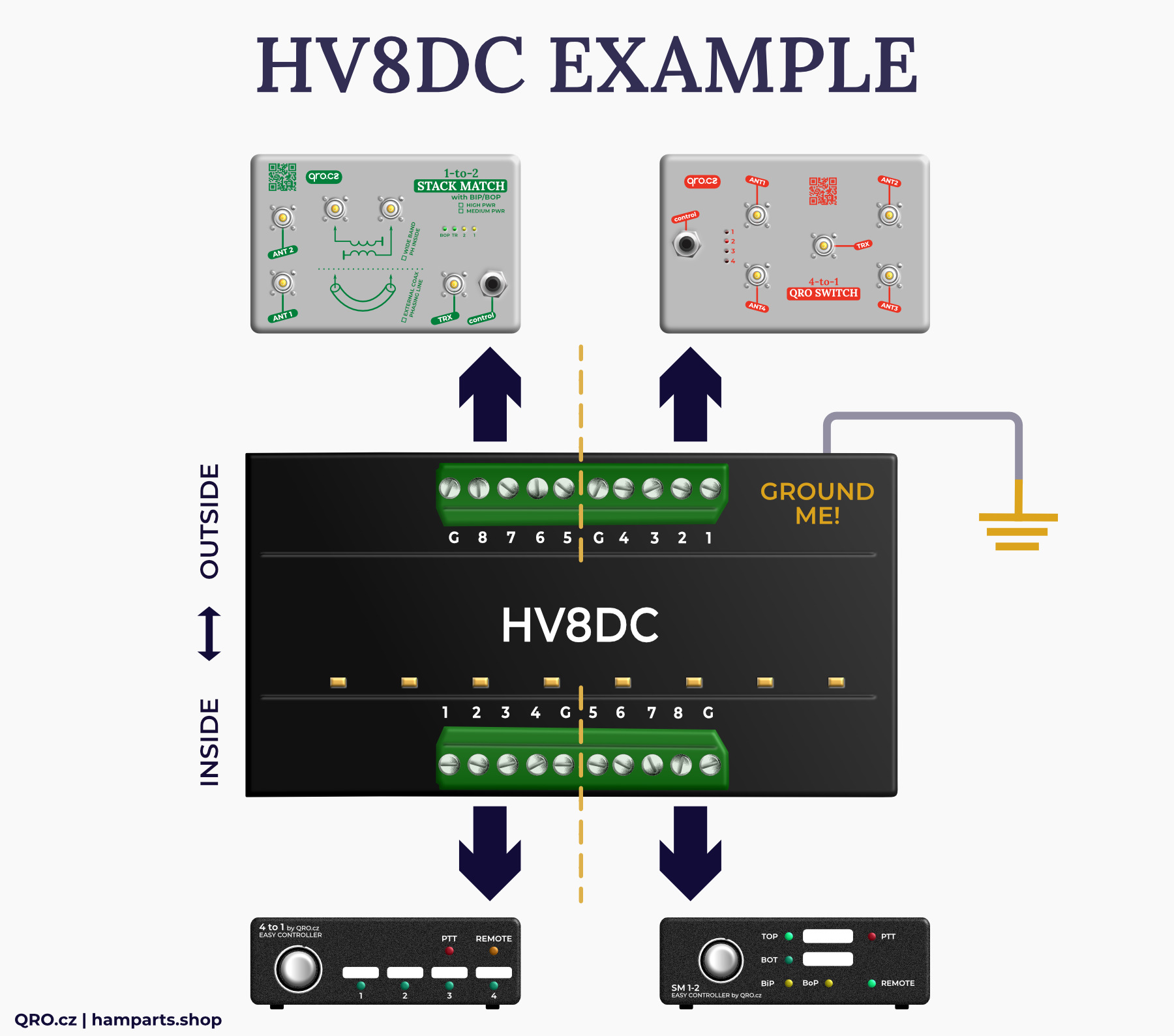
The eight control wires can also be split for multiple devices. For example for two Stack Match - 4 + 4 wires and GND or Stack match and 4-to-1 antenna switch. Here is an example:
⚠ NOTE! Be careful of the connections to the terminals. Inputs and outputs are the same numbers. So input 1 is output 1. input 2 is output 2, etc.
Parameters
- 8 DC control wires
- Only positive DC voltage
- DC up to 30V DC
- Current PTC fuse 0.6A
- GDT surge protection 75V
- Transil 40V DC
- High Voltage bridge fuse
- RFI low pass filter
- GDT to GND pin and GND screw
- LED diode at each CTRL wire
- Screw terminals
- DIN rail holder
- PCB size 135x72 mm

