BCD splitter manual

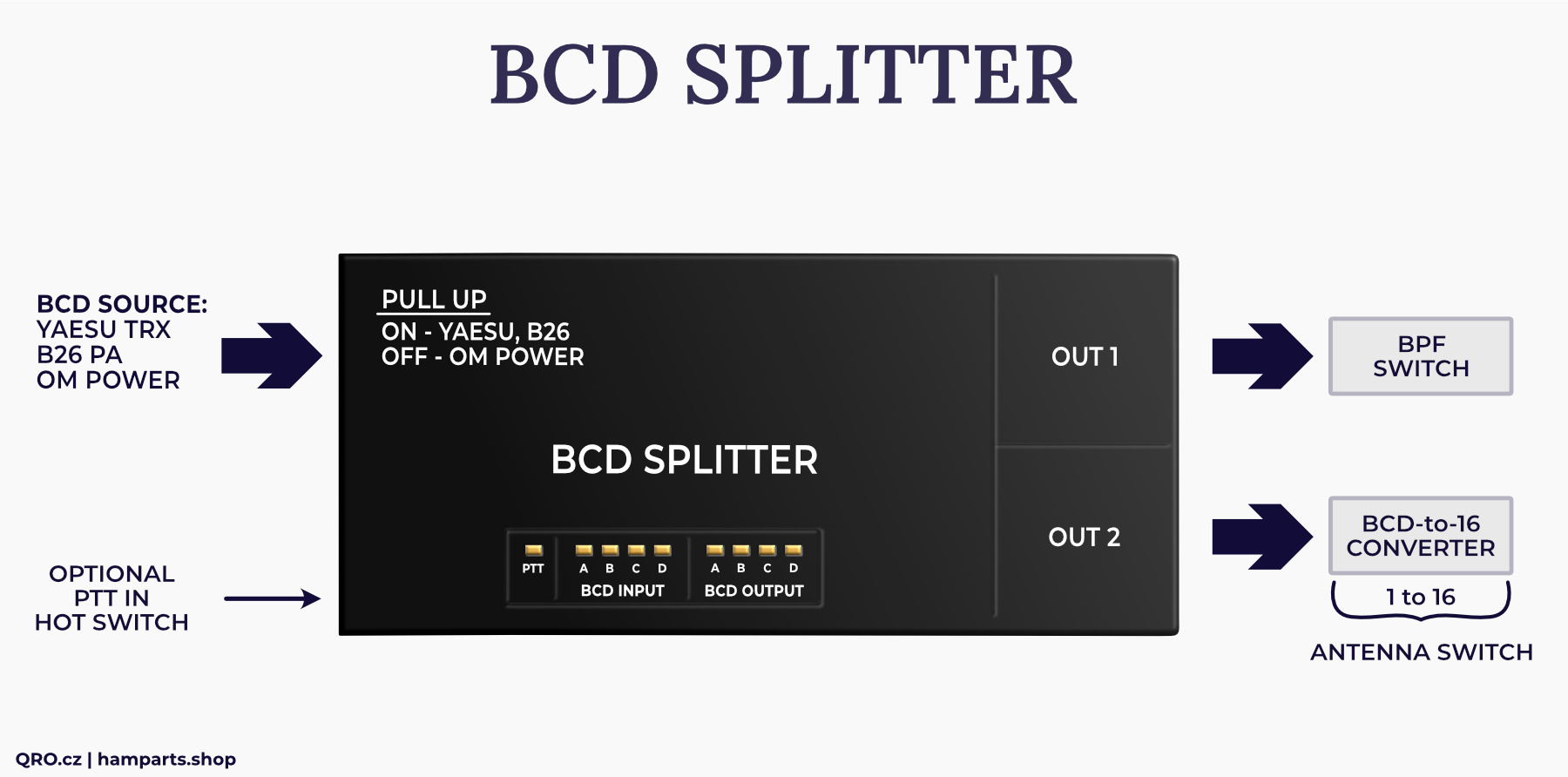
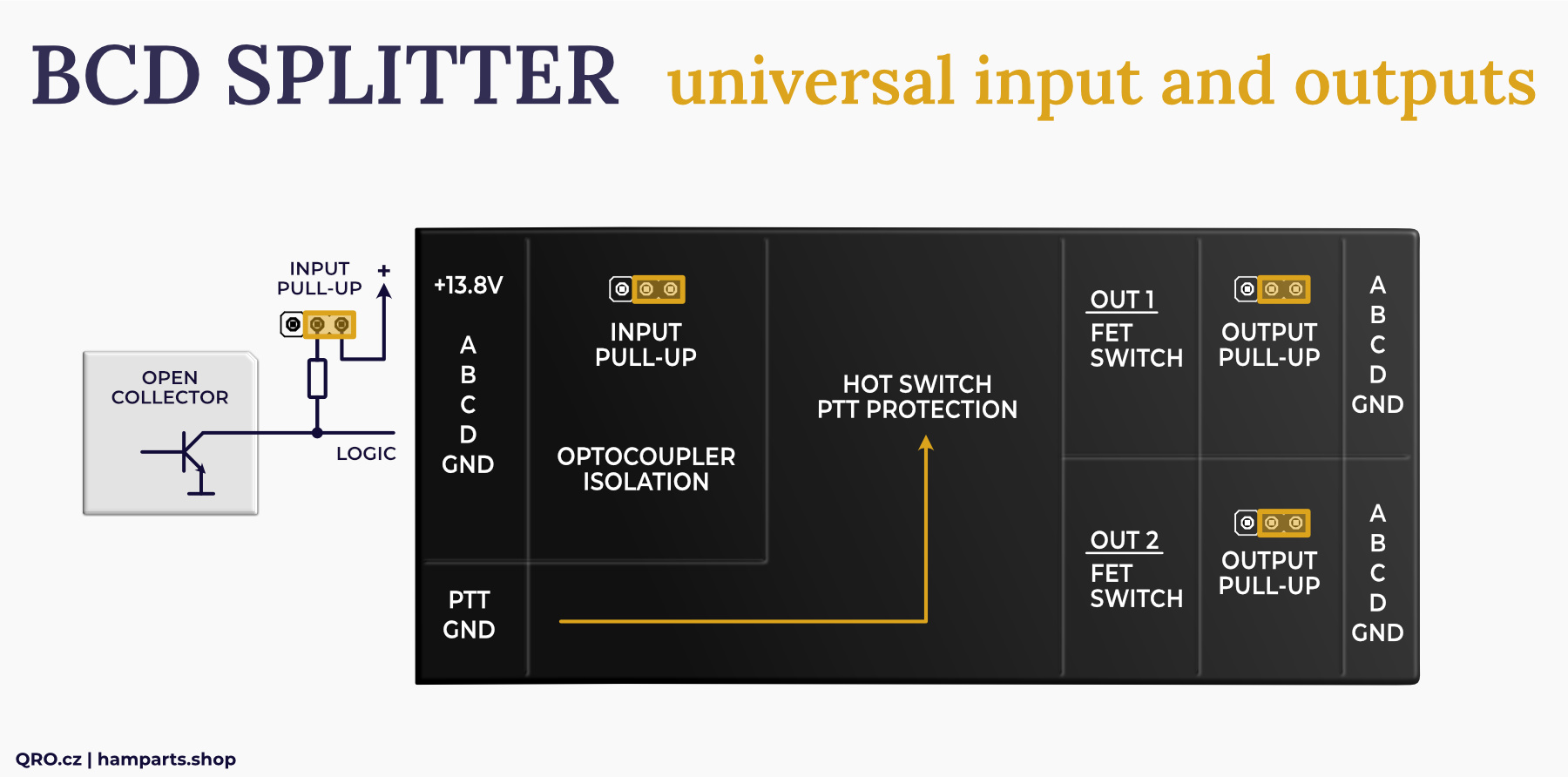
This is a simple but powerful board for splitting BCD Band Data from one input to two outputs. It allows you to split up to 4 bits from a universal input via optical isolation, 4 bit Latch (PTT hot switch protection) to two outputs. The outputs are equipped with FET transistors and switch to ground (open collector). The input and both outputs have the ability to turn on Pull-Up resistors, thus allowing cooperation with devices that use H or L signal control.
Jump to
Applications
Parameters
How to control the board
Pull-Up resistors
Open collector device
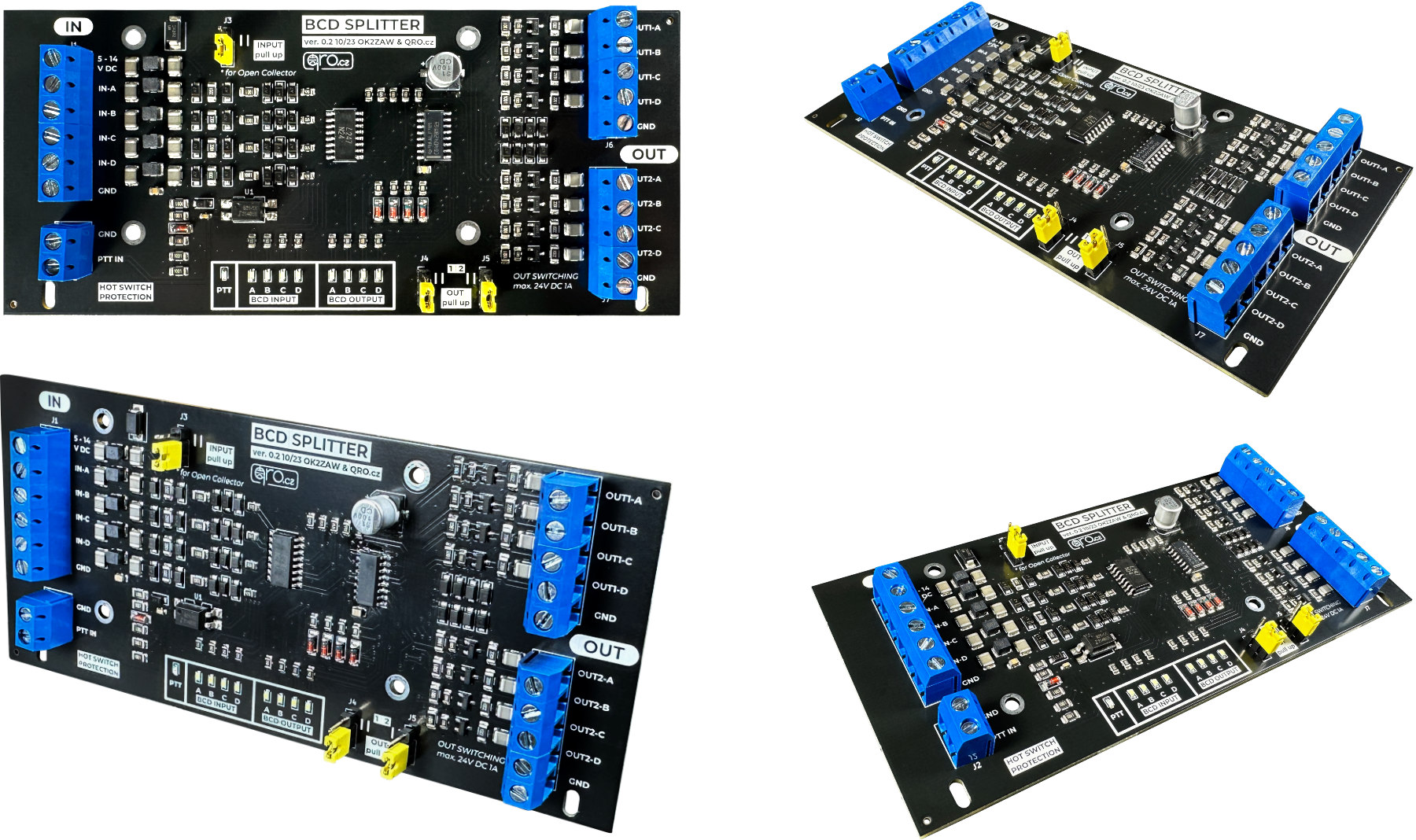
BCD Splitter board
Product details
Applications
The device has been developed for several reasons:
- BCD data source protection (optical separation)
- possibility to connect devices with Open Collector output as well as devices that send HIGH signal
- two outputs for two devices
- separation of two controlled devices
- PTT hot switch protection
- wide input voltage range
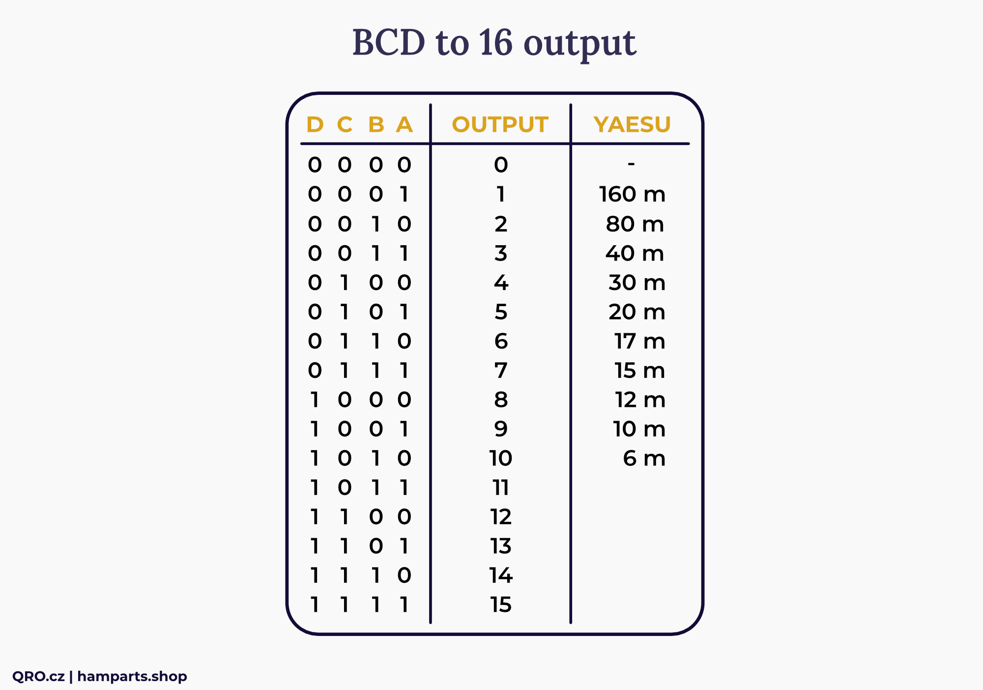
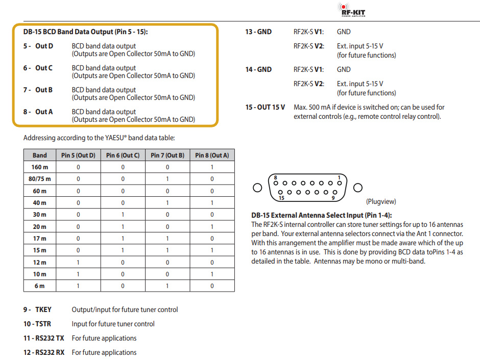
Example of the BCD band data matrix table (YAESU)
Parameters
- 4-bit BCD logic
- Input needs HIGH logic control
- Supply current up to 60mA @ 13.8V
- For Open Collector - Pull-UP must be set
- Input current for LOW control typ. 5.5mA
- HIGH control range 5 to 14.5V
- HIGH control when 13.8V connected:
- 1.8mA @ 3V, 3.7mA @ 5V, 10mA @ 12V
- Direct HIGH control, no 13.8V connected:
- 10mA @ 5V, 21mA @ 8V, 41mA @ 12V 1bit
- PTT hot switch: LOW = transmitting
- PTT current typ. 11mA
- Outputs FET max. 1A DC 24V
- Output Pull-UP resistor 2k2 from 12V
- PCB size 140x63 mm
How to control the board
- If the source of BCD data will be a device with Open Collector (switches to GND) it is necessary to connect to the board an external power supply of 13.8V (can be less, from 8V). It is also necessary to connect the input Pull-Up resistors - Jumper J3 (upper position).
- If the BCD data source is a device with a positive output voltage (HIGH), you can control the splitter directly. Depending on the voltage and allowable current of the source device. If the voltage is from 5 to 14.5V and the current is 10mA/5V to 41mA/12V per bit (half at 2 bits etc.), you do not need extra 13.8V to power the splitter. If the source device allows a smaller current load, you must connect an external power supply to the splitter.
- Hot switch PTT protection - usually the source device has protection against changing the BCD data during transmission (TRX), but if this protection is missing, some device could be damaged by changing the BCD state during transmission. In addition, the BCD splitter has this feature built-in. So, if you connect a PTT (TX = ground switch), the outputs remain set and ignore any input change.
Pull-Up resistors
Pull-Up resistors are activated to make the input/output logic HIGH. Then the source device switches to GND - logic LOW - device with open collector.
Output pull-ups are needed for devices that need to be controlled by logic levels H and L. An example is our BCD decoders (example BCD to 16).
Note: if you activate the input Pull-Ups and the input is disconnected or no BCD data is present, the input LEDs will indicate HIGH - lit. All input bits are set to logic HIGH.
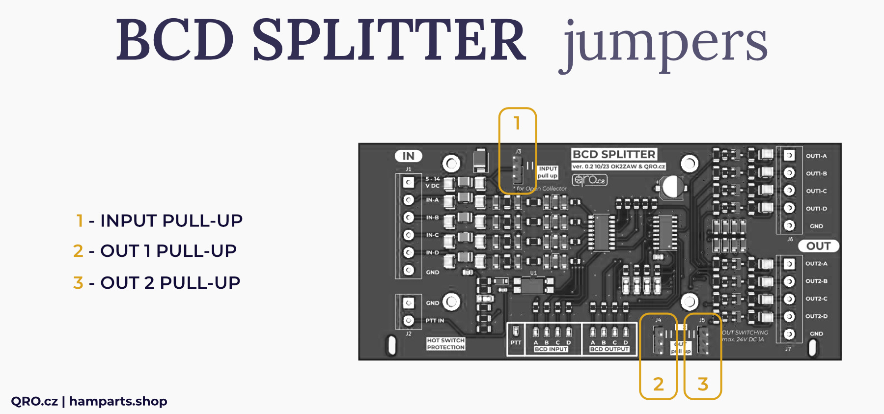
1. Input Pull-Up resistors
- Active when jumper is in top position. Connecting voltage to input BCD port. Use with devices with Open Collector.
2. Output 1 Pull-Up resistors
- When short - jumper in top position - voltage to output is connected over 2.2kOhm resistors
3. Output 2 Pull-Up resistors
- When short - jumper in top position - voltage to output is connected over 2.2kOhm resistors
How to know when to use Pull-Up Resistors:
- Connect the splitter input to the source device and 13.8V to the splitter board. If you don't see a change on the LED (none lit) when the BCD input changes, you can try turning on the input Pull Ups.
- The current through each input will be max 6mA when supplying 13.8V to the board.
⚠ ATTENTION! The input and output Pull-Up resistors are connected from the board supply voltage. Therefore, if the board is powered at 13.8V, this voltage is applied across the resistors (2k2) to the appropriate pin. If the BCD output were connected to a device with 5V TTL logic, the connected device could be damaged!
Open collector device
Devices with the open collector (like B26-PA RF2K-S) needs external pull up resistors. Short Jumper J3 (top position).
Compatible with OM-power amplifier Manual page 51 (ANT/BPF DB15).
R-KIT.de PA with the open collector (like B26-PA RF2K-S) connection + enable BAND data output in PA
BCD splitter board