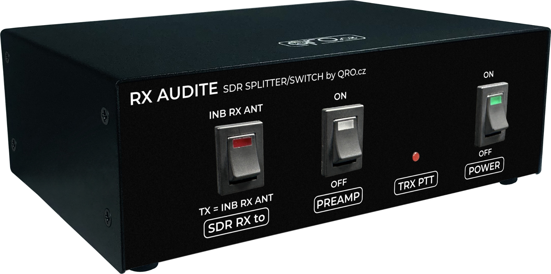
This controller is specially designed for 6 and 4m bands. It allows you to connect two RX to one antenna to monitor multiple band segments. It is possible to monitor multiple frequencies on one band (e.g. 50.313 and 50.323 FT8) but also frequencies on two bands - for example 6 and 4m (50.313 and 70.154 FT8). Using one dual-band Yagi antenna it is possible to monitor DX frequencies on both bands. In addition, this controller offers RF limiter protection for both RX outputs, filters limiting HF and FM BC frequencies, and a Low Noise Amplifier. One additional option is to connect an Inbound RX antenna for SDR RX when the TRX is transmitting.
There is a manual with a description of the device and wiring options.
Jump to
Technical information
Front panel description
Rear panel description
Low Noise Amplifier
Examples of the block diagrams
Jumper settings
FAQ
Product details
Technical information
Main functions
- Frequency range: 48 to 75 MHz
- Main TX/RX ANT splitter to two RX
- Low Noise Preamp
- Low and High pass filters
- RX RF limiter protections for both RX outputs
- High voltage and current protections at both RX outputs
- RX ANT (INBAND) input - works only for SDR output
- TX-RX switch controlled by the PTT
- Designed for 2nd RX, WEB-SDR, SKIMMER or Panadapter
- Controller OFF = TX/RX ANT port to SDR RX out via RF limiter protections - Skimmer/web-SDR
- Controller ON = TX/RX ANT port splitted to TRX and SDR RX out via RF limiter protections
- TRX TX to main TX/RX ANT = SDR RX out to dummy load or INBAND RX ANT input via RF limiter protections - see jumper switch
- Front panel Switch - SDR RX output to RX ANT (INBAND) during transmitting or all time
- Very high isolation when TRX transmitting and SDR goes to RX ANT (INBAND) typ. 78 dB @ 50 MHz and 75 dB @ 70 MHz
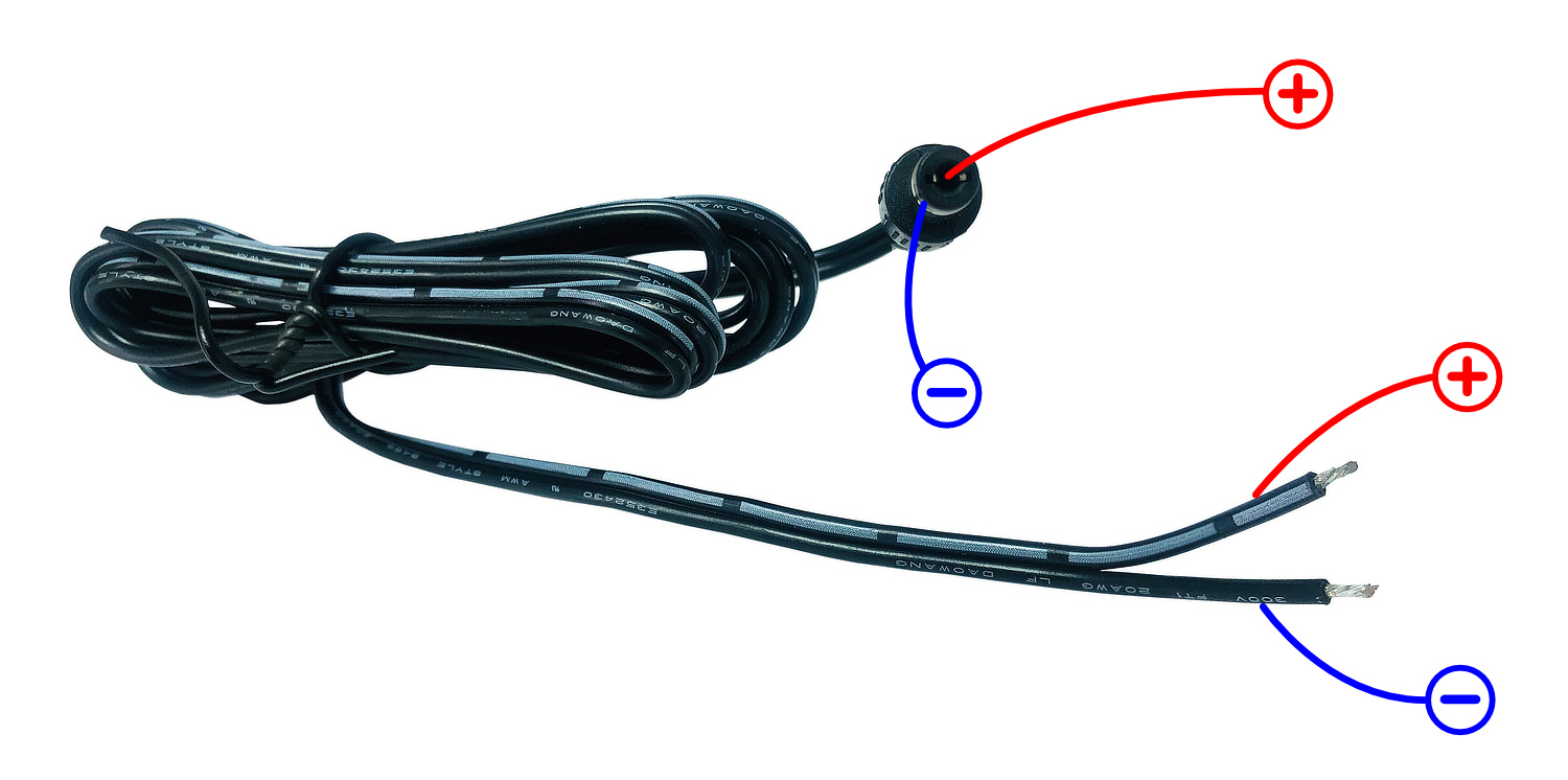
- DC plug included
- Preamplifier could be ON for SDR even controller is OFF
- Please, see also Frequently Asked Questions - FAQ
ONE black box but many different parts inside
- TX/RX with controlled by PTT signal
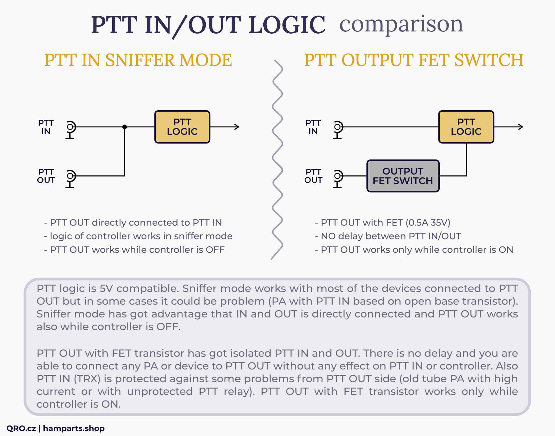
- PTT splitter (IN/OUT) in sniffer mode (IN directly to OUT) or output PTT FET switch - image
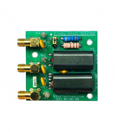
- 2-way RX splitter with low loss
- 2x RF limiter RX protections - the best on the market :)
- RX switch for RX ANT (INBAND) (only for SDR output) - settings
- Low and High pass filters (against HF and FM BC)
- RX preamplifier (high IP3, 25 dB gain) with variable ATT - manual link
- RX lines with High Voltage protections > 60 V AC
- RX lines with SuperFuse current protections > 100 mA
- Very high isolation TX to SDR, between RX output ports, INBAND RX and TX/RX ANT port
Parameters
- Frequency range: 48 to 75 MHz (6 and 4m)
- Supply voltage DC +12 to 14 V (13.8 V recommended)
- Supply current DC max. 0.7 A with preamp
- Maximal TX power 150 W, recommended 100 W
- LNA (PGA-103+): gain typ. 20 dB
- Noise Figure with LNA: typ. 1.1 @ 50 MHz, 1.3 @ 70 MHz*
- Filters: typ. -37 dB @ 28 MHz, -35 dB @ 99 MHz (LNA ON)
- Very high isolation when TRX transmitting and SDR goes to RX ANT (INBAND) typ. 78 dB @ 50 MHz and 75 dB @ 70 MHz
- PTT IN open PTT = RX, GND = transmitting
- PTT OUT sniffer (IN = OUT) or output FET (max. 35 V DC and 0.5 A) - image
- PTT is not designed for QSK but you can use with right PTT lead/tail/TX delay time: min. 20/20 ms
- Default configuration SDR to the internal dummy while TRX transmitting - settings
- Low insertion TX loss typ. Less than 0.15 dB
- RF connectors: N and SMA female
* include band filters and RF limiter
Front panel description
There are three switches with LED indication and red PTT LED
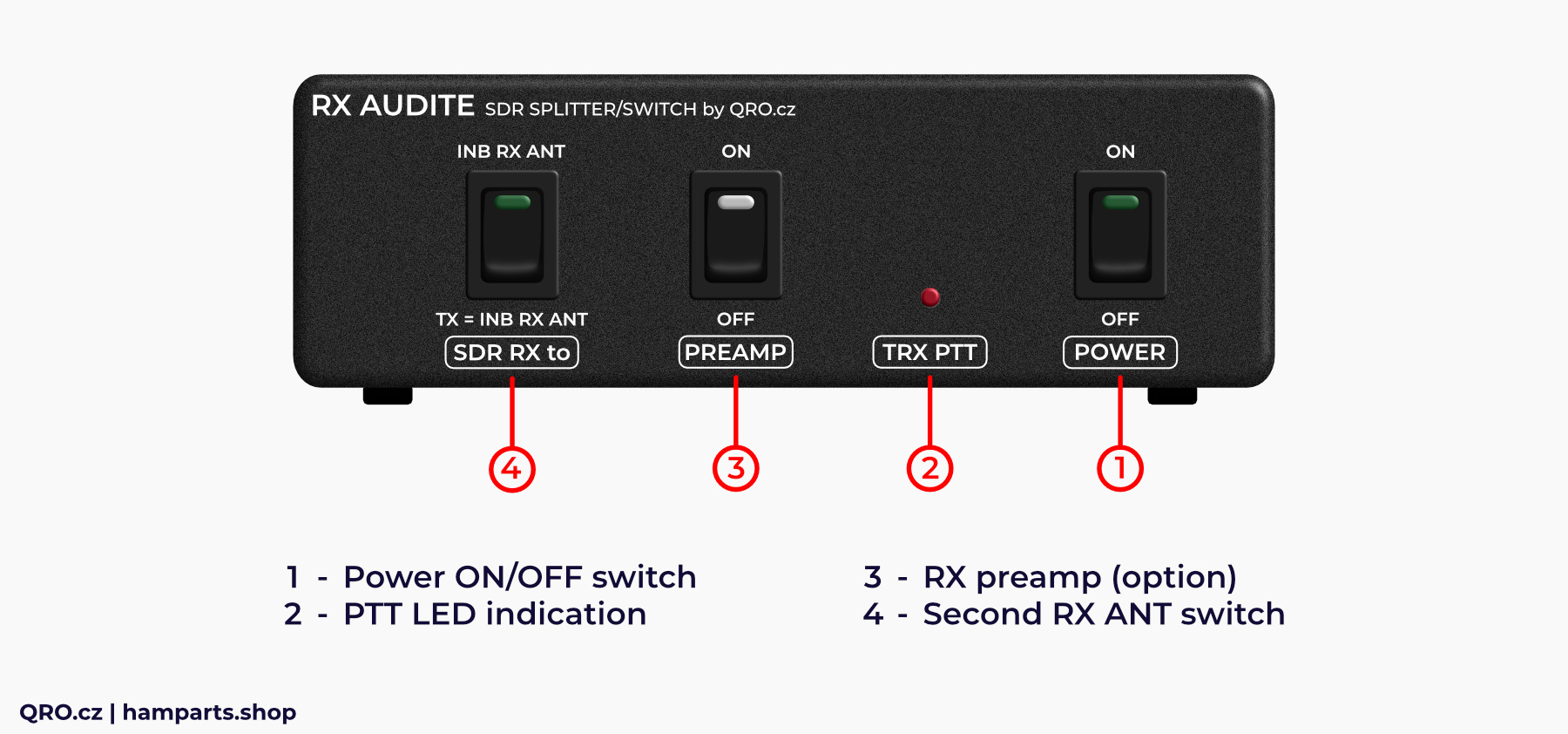
1. Power ON/OFF switch
- Even the Power Switch is OFF, you are able to switch ON the internal Preamp (Controller must be powered by the DC voltage)
- Signal from the main TX/RX ANT goes to the SDR RX output port. There are protections and RF limiter
2. PTT LED indication
- PTT indication
3. RX preamp module
- PREAMP ON/OFF
- Switch for internal Preamplifier
4. Second RX ANT switch - SDR RX to
- INB RX ANT: SDR OUT is connected to INB ANT input all the time (TRX RX of TX)
- TX = INB RX ANT: SDR OUT is connected to INB ANT input or dummy load while TRX is transmitting
Rear panel description
There are RF connectors: N and SMA, DC jack and RCA PTT IN and OUT
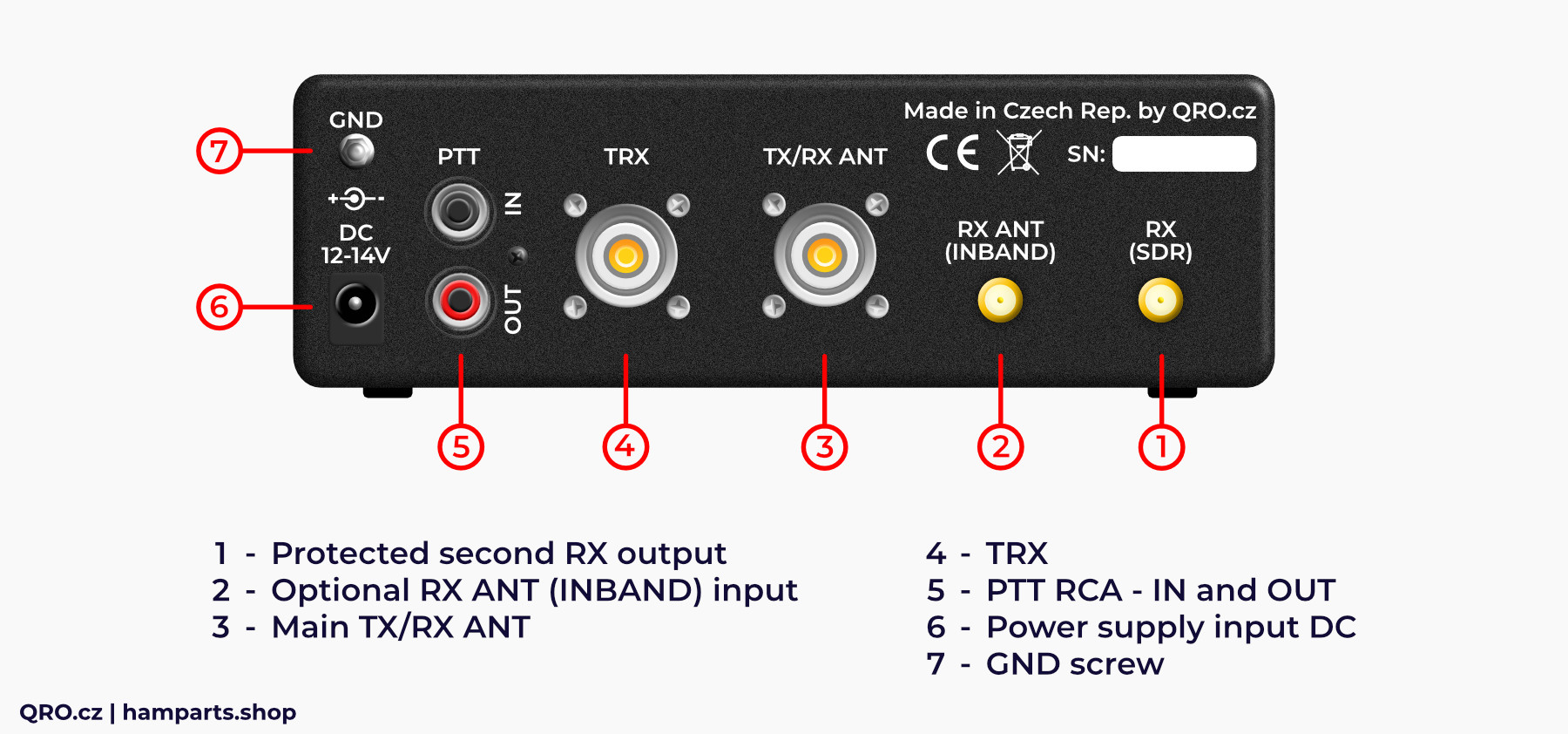
1. Protected second RX output
- RX output for second RX, SDR, skimmer etc.
- including protections and limiter
2. Optional RX ANT (INBAND) input
- Input for RX antenna for SDR output
- Could be used while TRX is transmitting or all the time
3. Main TX/RX ANT
- Main TX and RX antenna
- TX for TRX
- Shared for TRX and SDR output
- When the controller is OFF - this antenna is connected to SDR out
4. TRX
- TRX port
- RX protections included
5. PTT RCA - IN and OUT
- PTT IN from TRX (station controller)
- IMPORTANT for the right function
- PTT out for PA or another device
- NO delay between PTT IN and OUT
6. Power supply input DC
- DC input
- DC 13.8 V recommended
7. GND screw
- connection for common ground in hamshack
⚠ PLEASE, do not forget to connect PTT from your TRX. This controller does not have VOX, you have to connect TX information from your TRX. PTT OUT has got no delay. There is internal PTT splitter and you can connect another device there (PA).
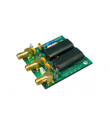
Low Noise Amplifier
An internal Low Noise Aplifier (LNA) improves the noise performance of the device and eliminates internal protection and 2-way splitter losses. In addition, it includes a low pass filter that attenuates frequencies above 75 MHz - local FM radio TX. The preamplifier module includes a thirty turn trimmer for gain adjustment. The total gain can be over 20dB which can sometimes be a lot so the gain can be reduced to the required level.
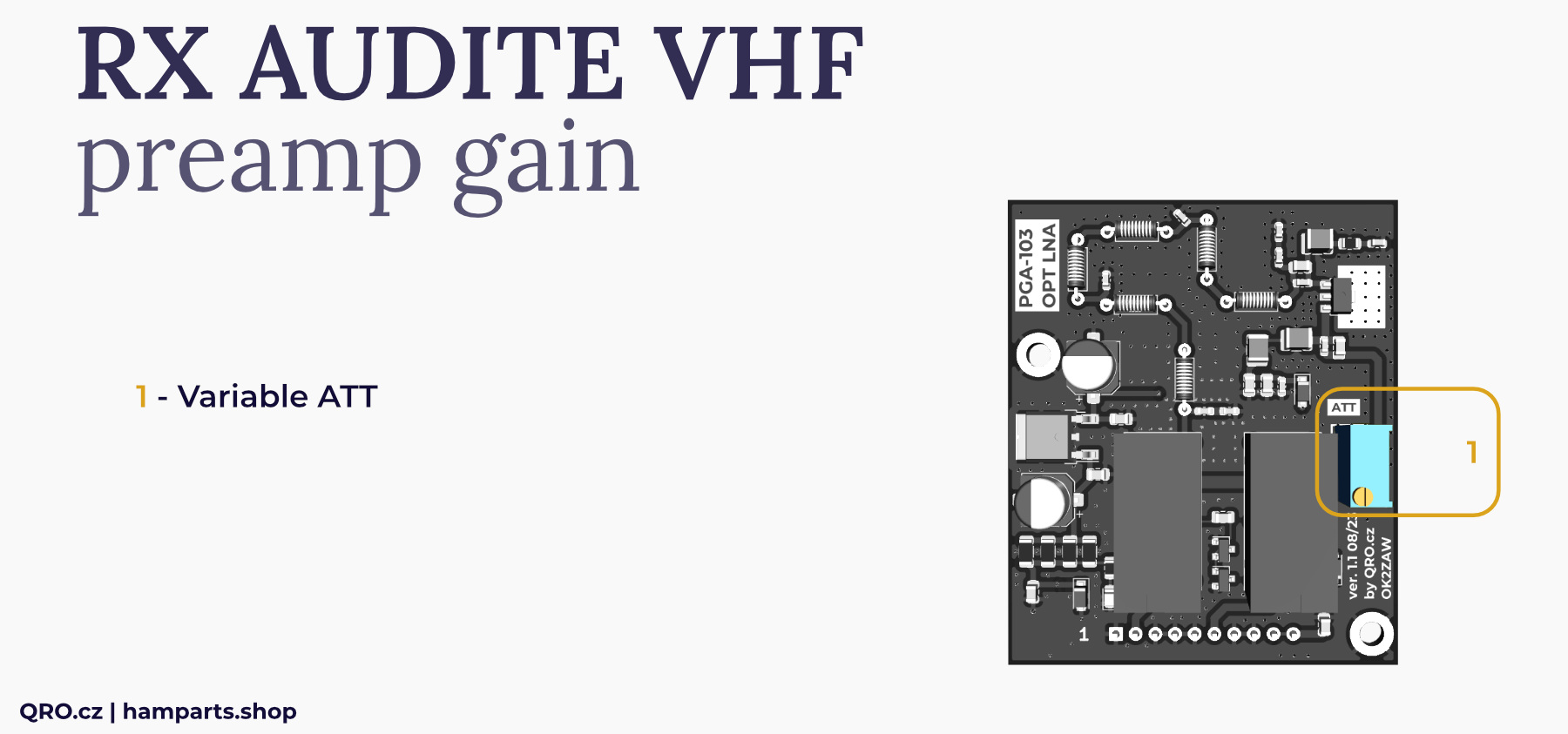
1. Variable ATT
- with the resistor trimmer ATT you can set amplifier gain as you need form 0 to about 25 dB
- turn the ATT - multi turn trimmer
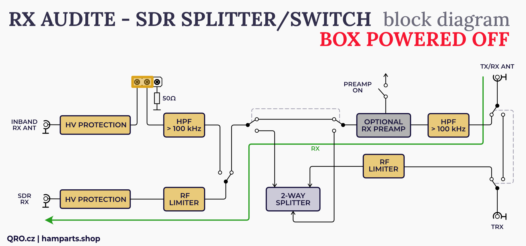
Examples and block diagram
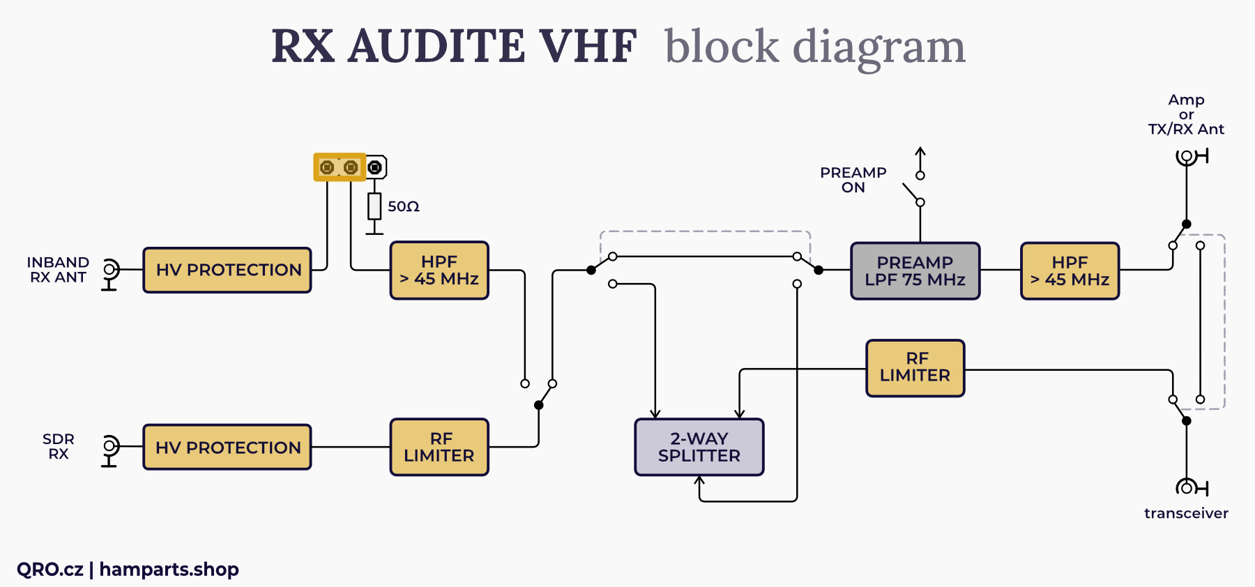
There is a block diagram of RX AUDITE VHF. When the device is turned off, the signal from the TX/RX antenna goes to the SDR output. The signal passes through HV protection, HPF 45 MHz, RF limiter, LNA (when LNA is on, LPF 75MHz is also included) and output RF limiter.
When the device is turned on, the 2-way splitter is activated and the signal is split into TRX and SDR outputs. Both outputs have an RF limiter. When the front panel switch "SDR RX to" is switched to the INB RX ANT position, the splitter is disconnected and the RX signal goes from the TX/RX antenna directly to the TRX. The SDR is connected to the internal dummy load or to the Inband antenna.
When transmitting (PTT must be connected to TRX), the signal from TRX goes directly to TX/RX antenna. The SDR is connected to the internal dummy load or to the Inband ANT input (depending on the setting of the internal jumper).
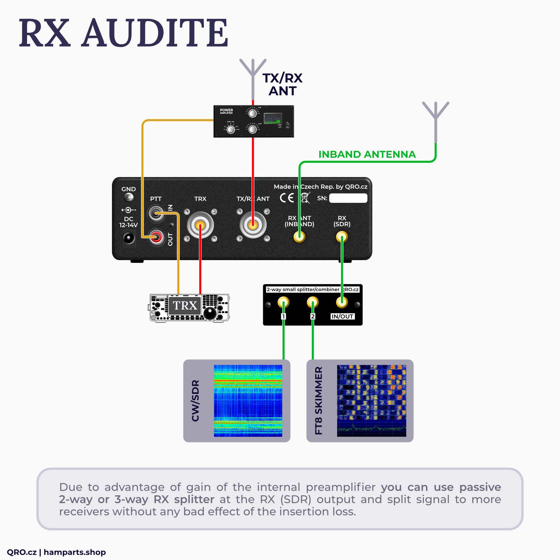
RX Audite with the internal LNA board and variable gain eliminates insertion loss of the internal RX splitter and also allows you to connect external splitter for two or three RX at the RX (SDR) output port.
Example 1: Dual watch at 6m
You can watch one segment at TRX and second at SDR. For eample SSB DX window at TRX and 50,313 MHz FT8 at SDR. This can help you to check DX propagation. This example also allows you to watch both FT8 segments: 50,313 and 50,323.

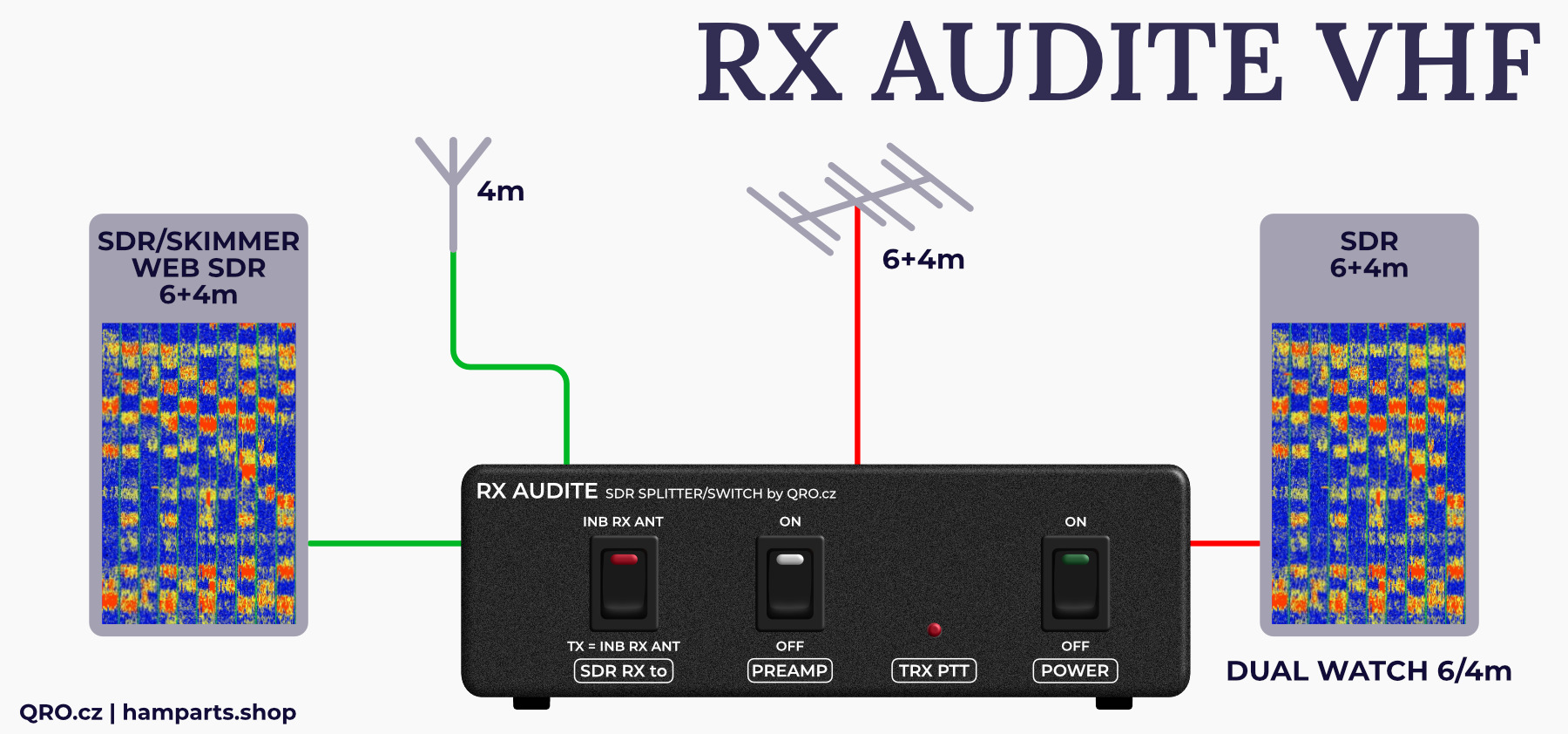
Example 2: Dual watch at 6m and 4m
You can share one dual band Yagi antenna into 6m a one RX and 4m into a second one. You can monitor FT8 segments at 6 and 4m.
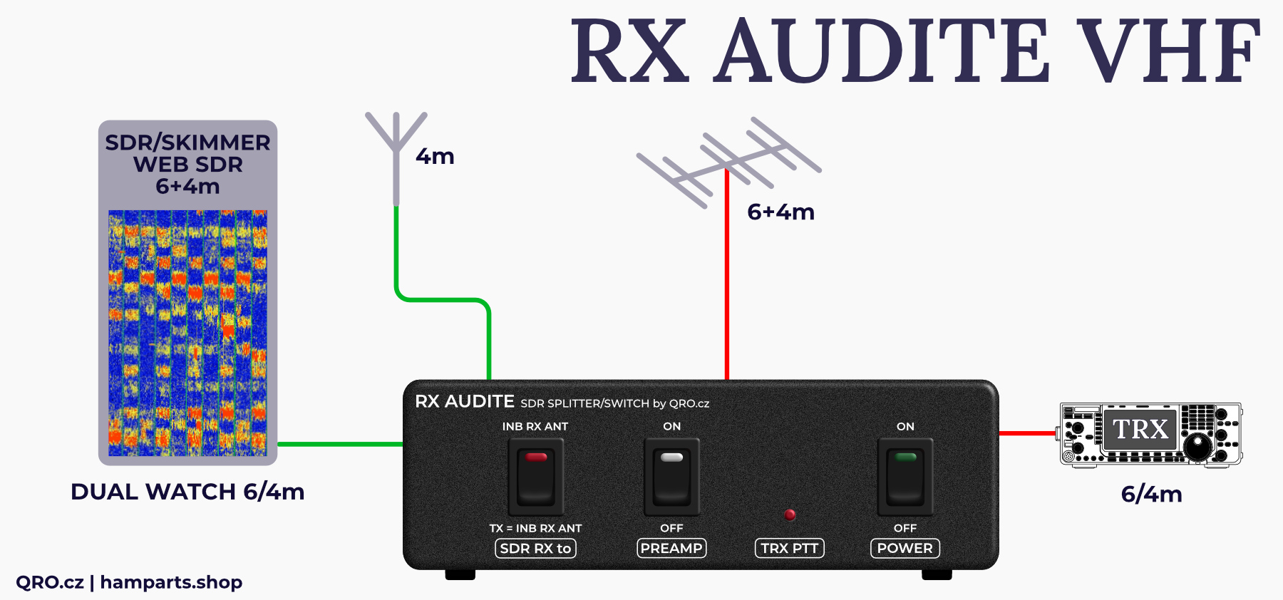
⚠ You can use OPTIONAL INBAND ANT for SDR RX while the TRX is transmitting. This could work only when the antennas have got good isolation ort he INBAND antenna is single band or have a BPF. For example you are able to TX at 6m and SDR can RX at 4m from INBAND RX ANT during that time.
Example 3: Two SDR RX - WEB SDR, skimmer SDR TRX
You can use RX AUDITE VHF as a RX splitter with protections and Low Noise Preamplifier.
Jumper settings
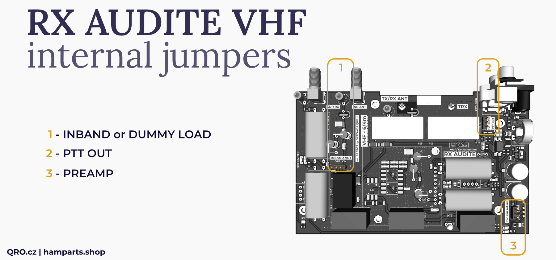
1. INBAND or DUMMY LOAD
SDR output could be connected to Inband RX antenna or internal 50 Ohm dummy load. When you do not use Inband RX antenna, please set this jumper to internal dummy load or connect external small dummy load to Inband SMA connector.
2. PTT OUT
- Selecting between sniffer mode and PTT FET
- Please, see next picture with an explanation
- default is FET output
3. PREAMP ON/OFF
This jumper allows you to switch preamp only while the controller box is ON (main power switch is ON) or you can switch preamp independently on main power ON switch and use preamp also while the controller is OFF (this is in case you want to have preamp for SDR all time ON).


