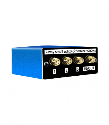
RX Audite SDR Switch manual
With this device, you can add a Panadapter, WebSDR, or skimmer to your amateur radio equipment. You can also compare different receivers, add SDR functions to your classic TRX, etc. With an emphasis on receiver protection and a number of safeguards, this device is unique. The built-in preamplifier compensates for RX splitter losses and can add 1-2 S units to the signal. This manual provides a more detailed description of the functions and measurements.
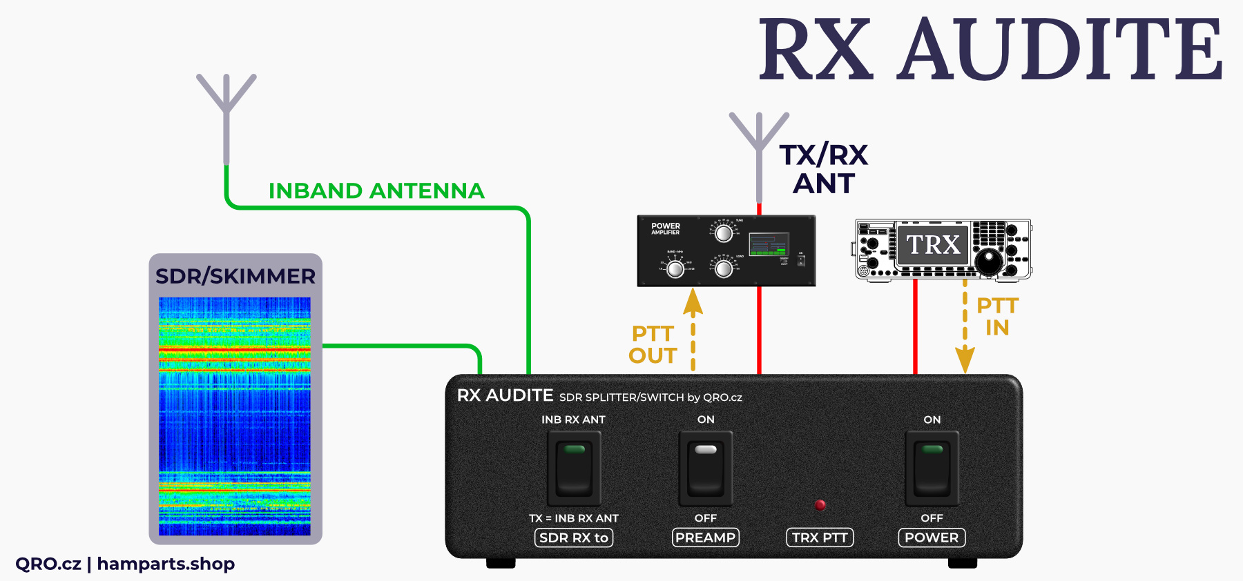
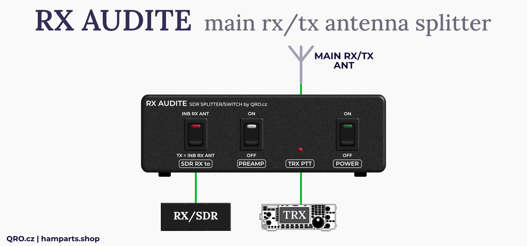
This controller was designed for antenna sharing to the TRX and CW/RTTY/FT8 skimmer for RBN network.
ONE black box with these incredible parts:
Although the price of the device may seem high, it contains several protection systems that could save you much more in the long run. The main feature is the RF limiters, which protect both receivers’ outputs. If a strong signal appears at the receiver input, it can cause irreversible damage. These protections are especially important for SDR receivers with ADC converters connected to the antenna, as they limit the maximum signal size and thus protect the receivers. Even in the event of a PTT malfunction or incorrect transmission to the antenna input, these protections safely limit the RF signal strength and prevent damage to the receivers.
- TRX/RX switch controlled by PTT signal
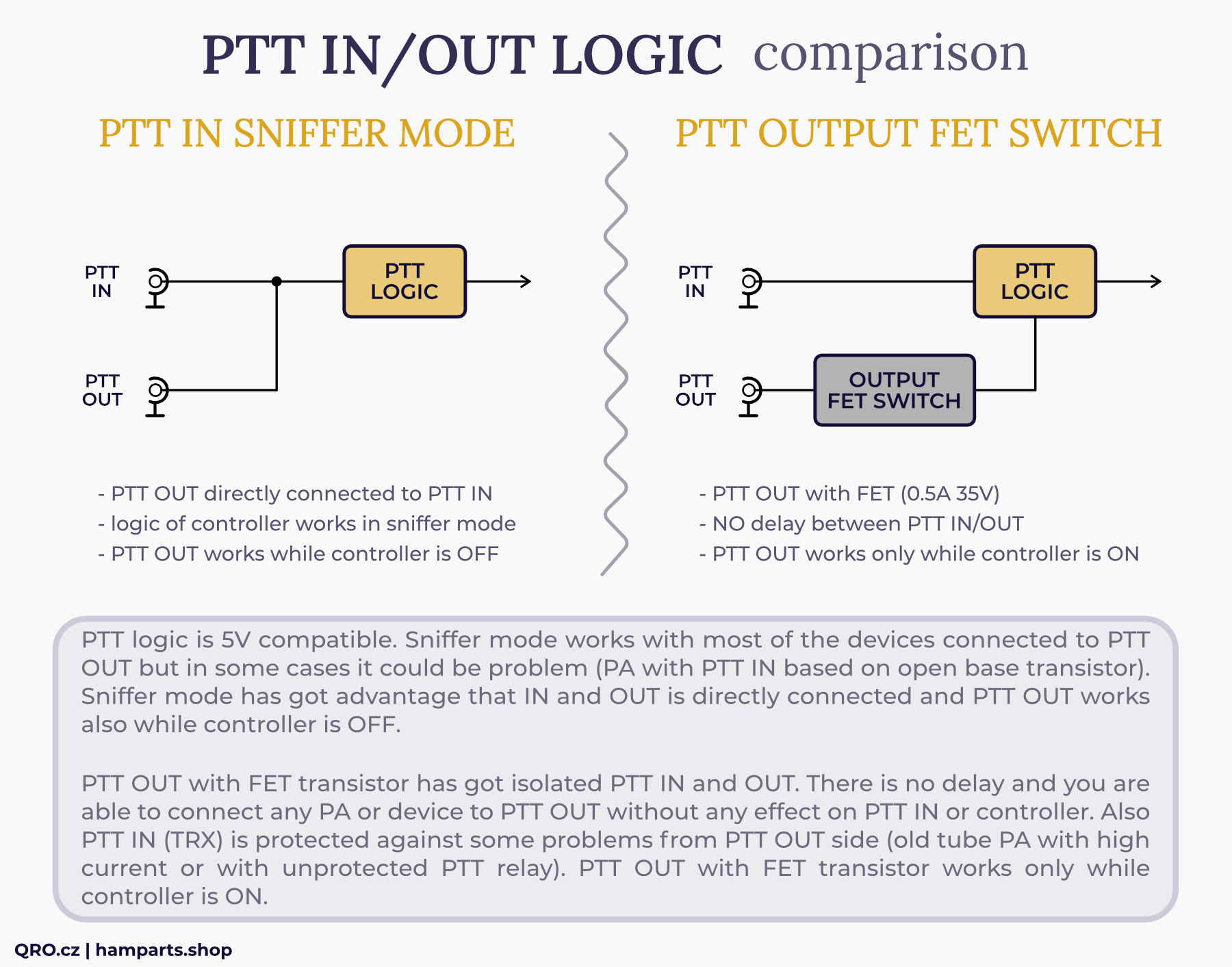
- PTT splitter (IN/OUT) in sniffer mode (IN directly to OUT) or output PTT FET switch - image
- 2-way rx splitter with low loss
- 2x RF limiter rx protections which is the best on the market :)
- RX switch for RX ANT (INBAND) (only for SDR output) - settings
- Both antennas with HPF > 100 kHz (blocking AC noise)
- RX preamplifier (high IP3, 18 dB gain) with variable ATT - manual link
- RX lines with High Voltage protections > 60 V AC
- RX lines with SuperFuse current protections > 100 mA
- Very high isolation TX to SDR, between RX ports, INBAND RX and TX/RX ANT port
Jump to
Front panel description
Rear panel description
Comparison
Optional preamp module
Installation
Examples of the block diagrams
Jumper settings
RF limiter
Own TX signal at SDR out
Measurement
FAQ
Previous versions
Product details
Front panel description
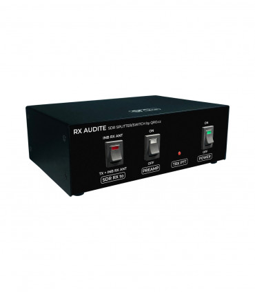
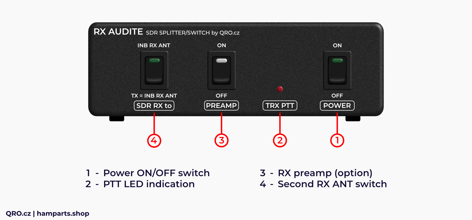
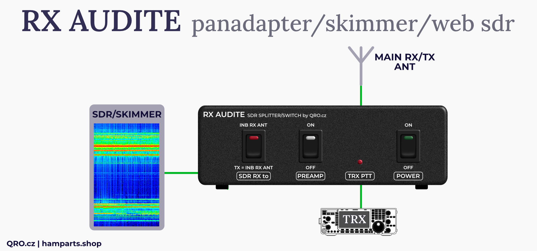
There are three switches with LED indication and red PTT LED
1. Power ON/OFF switch
- Even the Power Switch is OFF, you are able to switch ON the internal Preamp (Controller must be powered by the DC voltage)
- Signal from the main TX/RX ANT goes to the SDR RX output port. There are protections and RF limiter
2. PTT LED indication
- PTT indication
3. RX preamp module (option)
- PREAMP ON/OFF
- Switch for internal Preamplifier (optional or model with preamp)
4. Second RX ANT switch - SDR RX to
- INB RX ANT: SDR OUT is connected to INB ANT input all the time (TRX RX of TX)
- TX = INB RX ANT: SDR OUT is connected to INB ANT input or dummy load while TRX is transmitting
Rear panel description
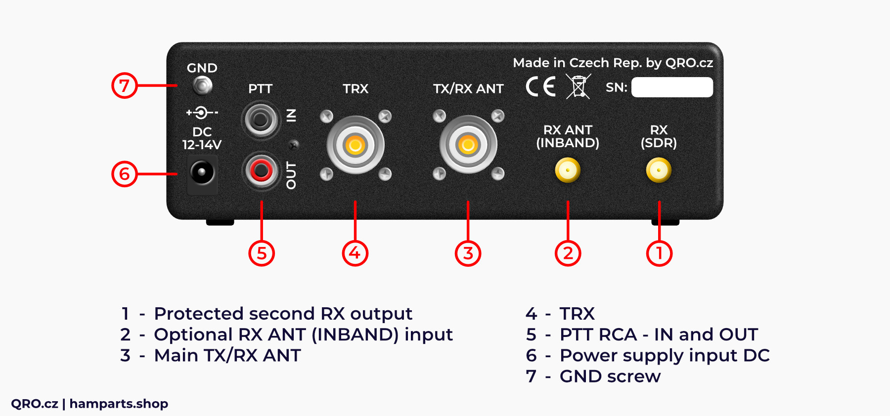
There are RF connectors: SO-239 and SMA, DC jack and RCA PTT IN and OUT
1. Protected second RX output
- RX output for second RX, SDR, skimmer etc.
- including protections and limiter
2. Optional RX ANT (INBAND) input
- Input for RX antenna for RX (SDR) output only
- Could be used while TRX is transmitting or all the time
3. Main TX/RX ANT
- Main TX and RX antenna
- TX for TRX
- Shared for TRX and SDR output
- When the controller is OFF - this antenna is connected to SDR out
4. TRX
- TRX port
- RX protections included
5. PTT RCA - IN and OUT
- PTT IN from TRX (station controller)
- IMPORTANT for the right function
- PTT out for PA or another device
- NO delay between PTT IN and OUT
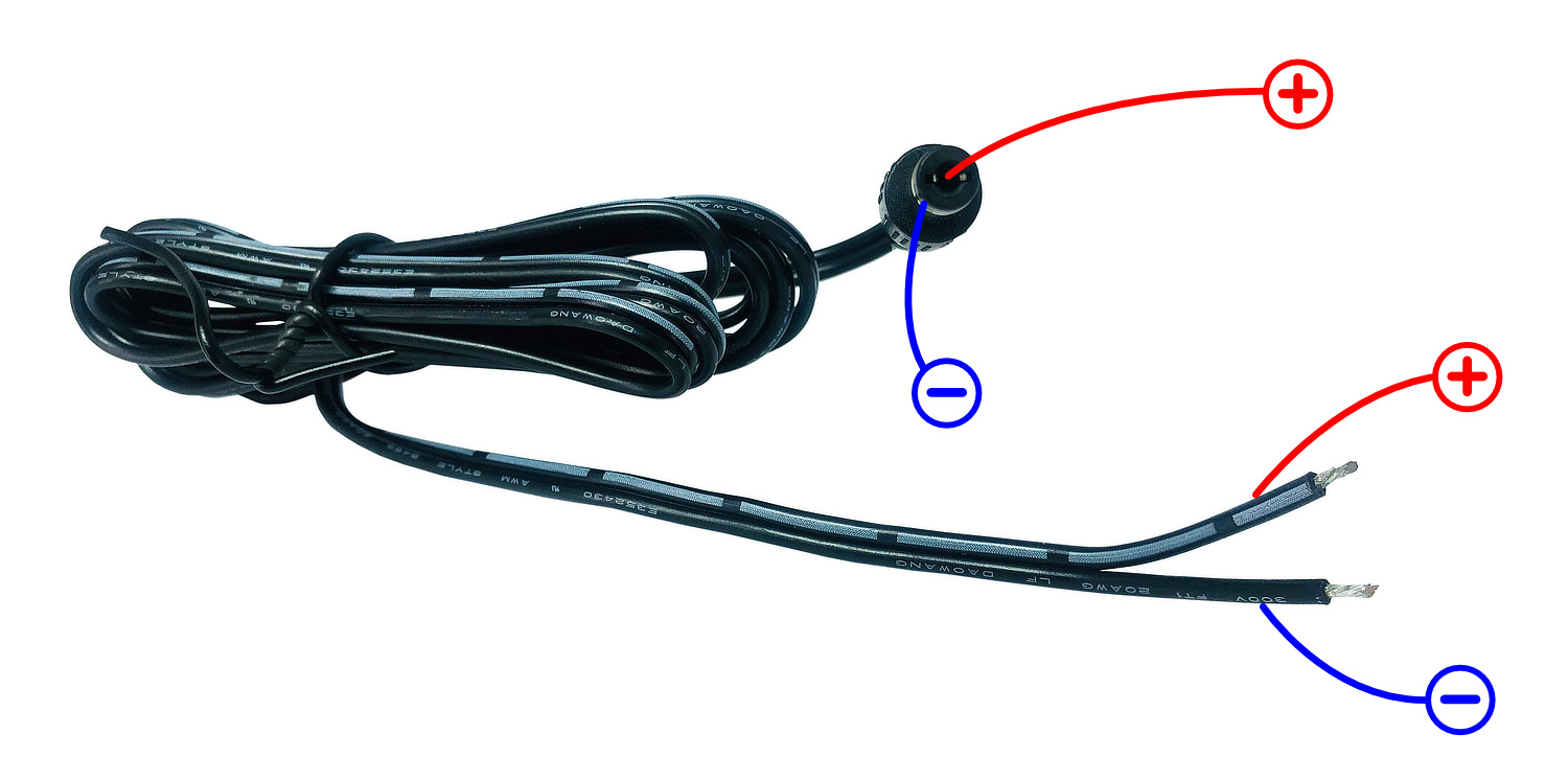
6. Power supply input DC
- DC input
- DC 13.8 V recommended
7. GND screw
- connection for common ground in hamshack
⚠ PLEASE, do not forget to connect PTT from your TRX. This controller does not have VOX, you have to connect TX information from your TRX. PTT OUT has got no delay. There is internal PTT splitter and you can connect another device there (PA).
Comparison
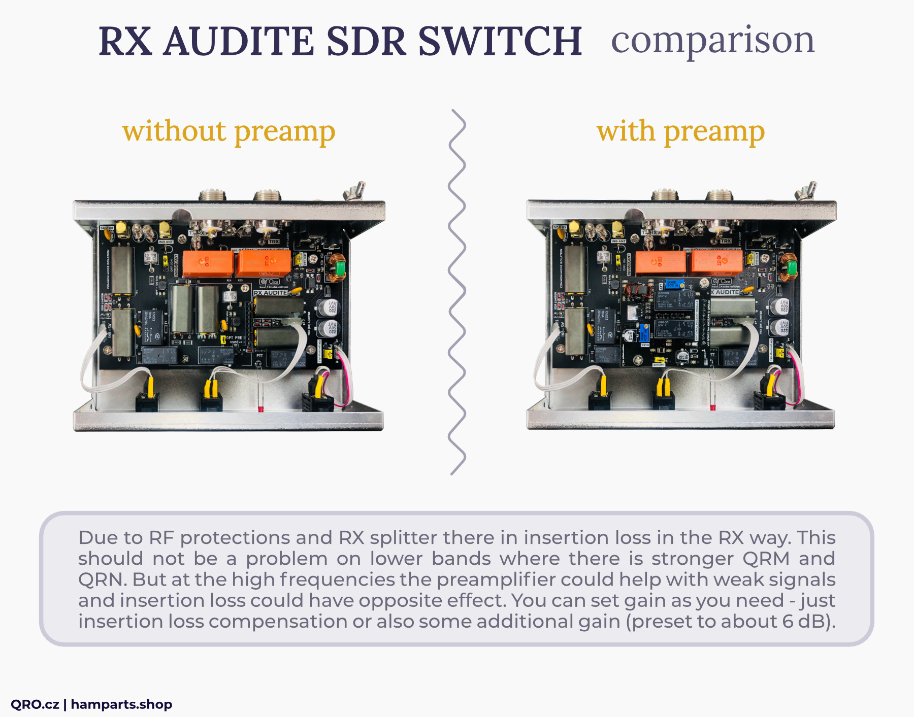
There are/were two versions, the first is without internal RX preamplifier and second one with it. This preamplifier could be added later too - for version without preamp. This is wide band high IP3 preamplifier module. This RX preamplifier could help with insertion loss (protections, splitter etc.). You can set gain as you need. It is preset to 10 dB, what is IL +6 dB of the additional gain.
Since MK3 version (SN: 2506xxxx and higher) there is only version with PREAMP INCLUDED.
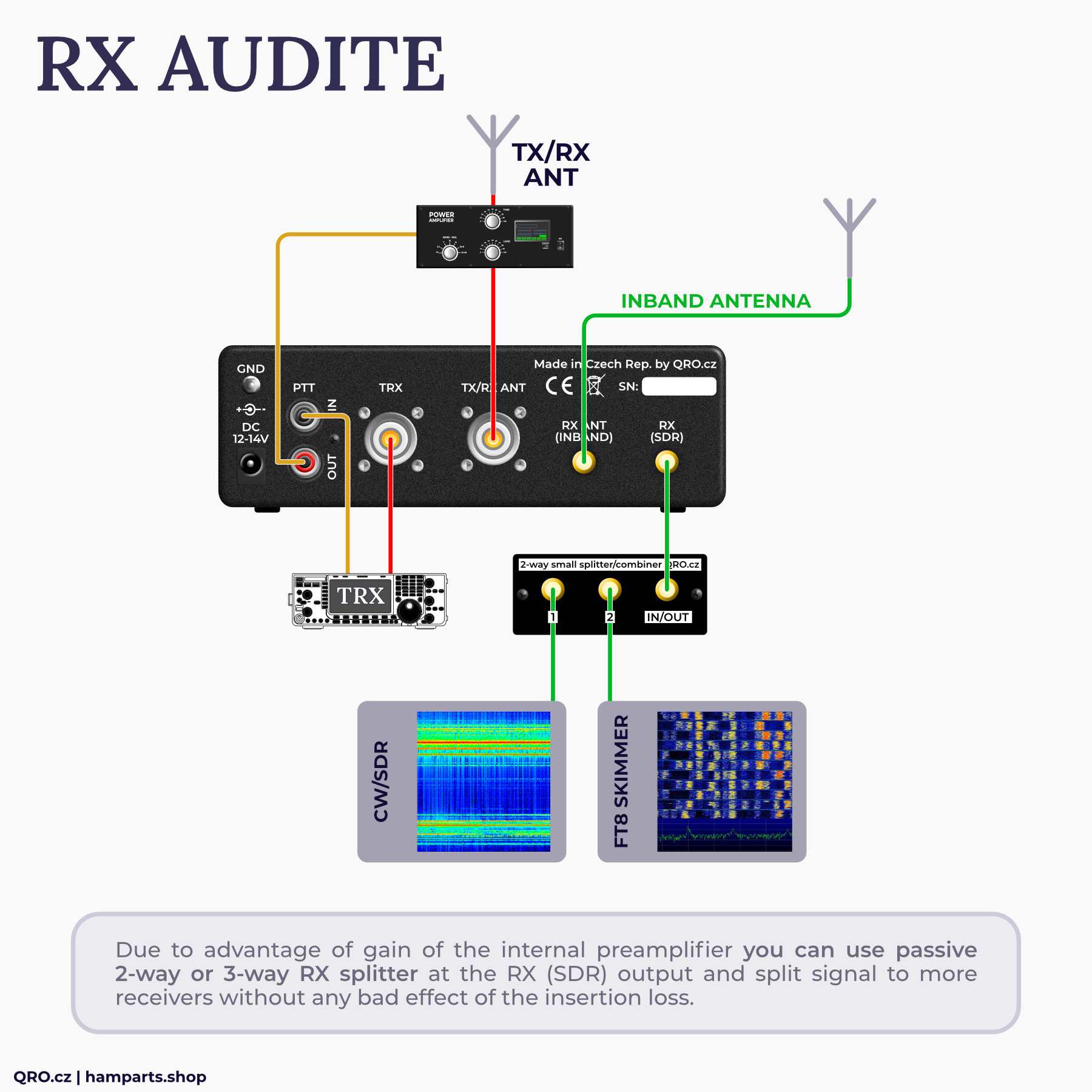
RX Audite with the internal preamplifier board and variable gain eliminates insertion loss of the internal RX splitter and also allows you to connect external splitter for two or three RX at the RX (SDR) output port.
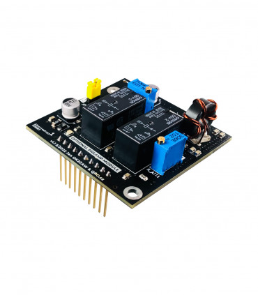
Optional preamp module
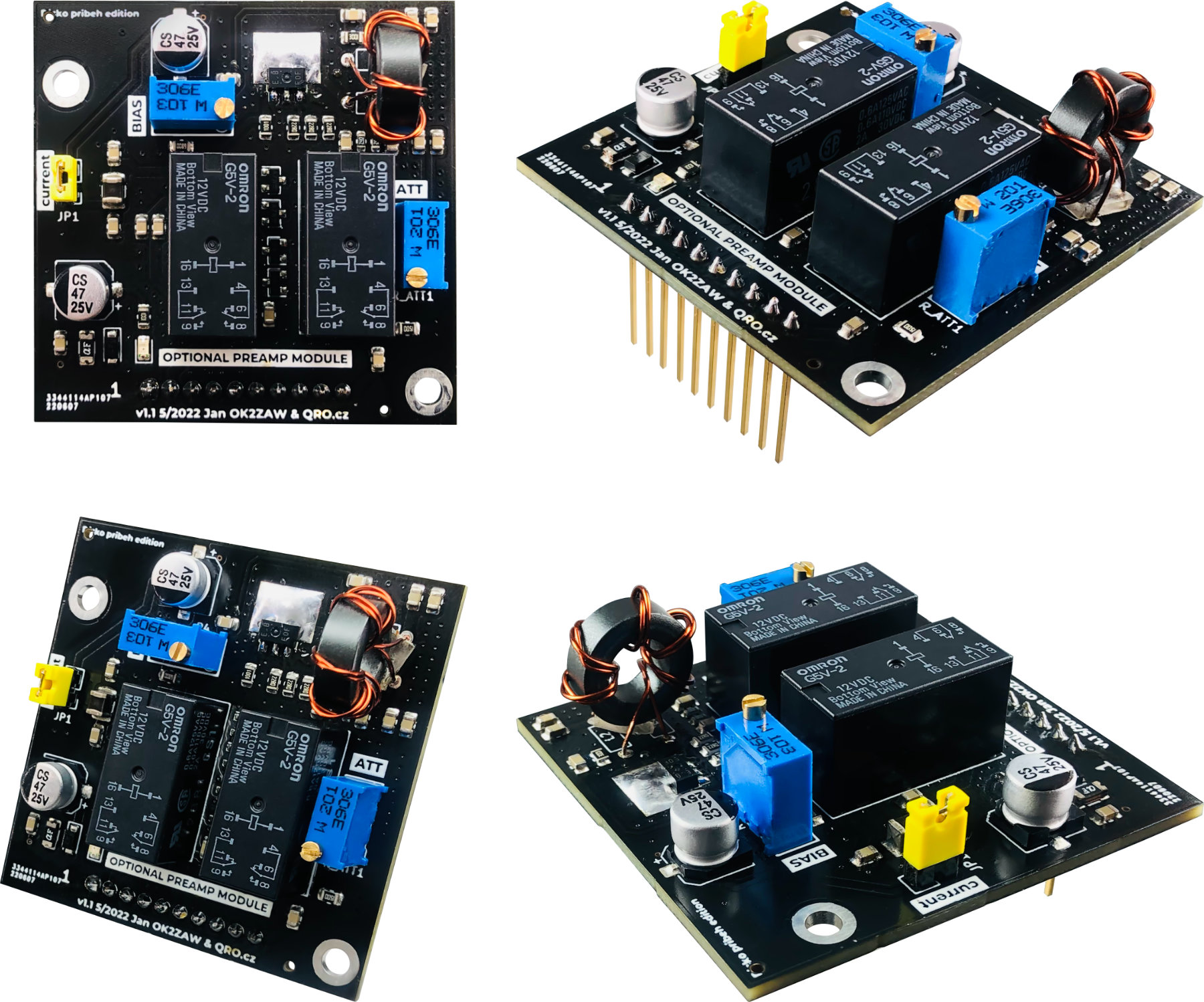
Internal preamp could be used to eliminate controller insertion loss. It can also improve SDR sensitivity, especially in higher bands. Thanks to variable ATT you can comfortable gain value as you need. This optional preamp module could be installed also later as an option. Since MK3 version (SN: 2506xxx and higher) there is only version with PREAMP included.
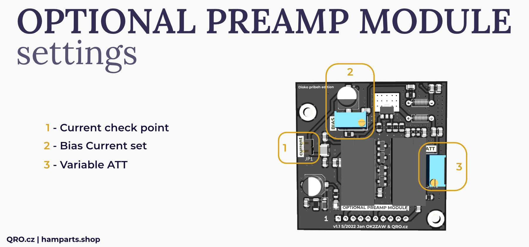
1. Current check point
- disconnect jumper JP1
- connect mA meter there (200 mA scale is fine)
- connect supply voltage to the controller (13.8 V)
- switch preamp ON by front panel switch
2. Bias Current set
- turn the resistor trimmer BIAS and set bias current - it should be around 30 mA
- then connect jumper JP1 back
3. Variable ATT
- with the resistor trimmer ATT you can set amplifier gain as you need from 0 to about 18 dB
- turn the ATT (R_ATT1 201) - multi turn trimmer
Installation
- disconnect the device from cables and power
- open the device - remove the top cover
- remove the two screws in the place of installation of the preamp module
- screw two spacer bolts (sleeves) instead of these screws
- tighten slightly
- remove the jumper marked OPT PRE used (point 2 at this manual)
- insert the preamplifier module into the pin header
- check the insertion of all ten pins
- screw in the two screws for fixing the module
- connect the power supply and turn on the preamplifier switch on the front panel
- check if the yellow LED on the module is lit
- connect all cables and test the gain
- if you need, it is possible to increase or reduce the gain (Variable ATT at this manual, image)
- install the top cover and the assembly is complete
Examples of the block diagrams for all functions
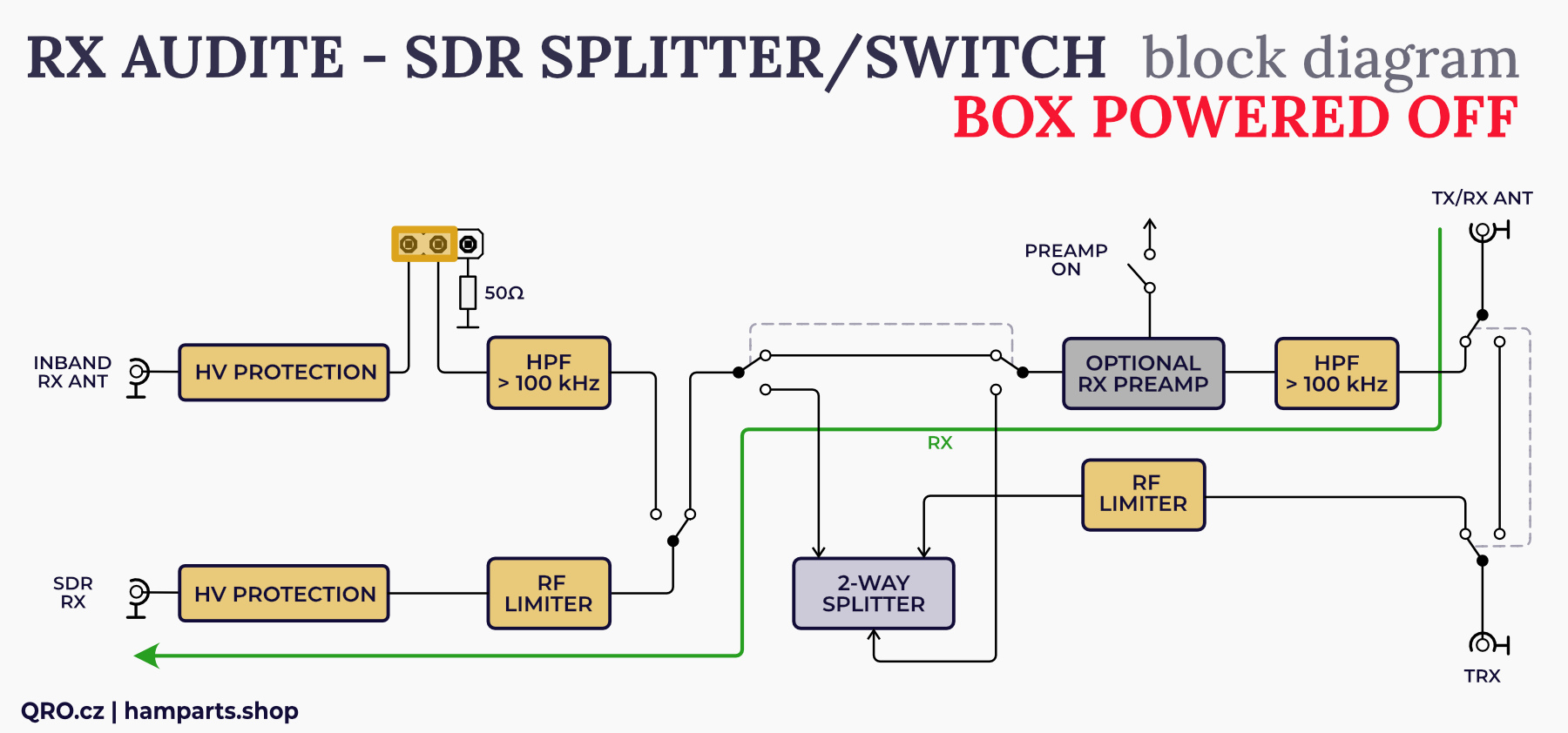
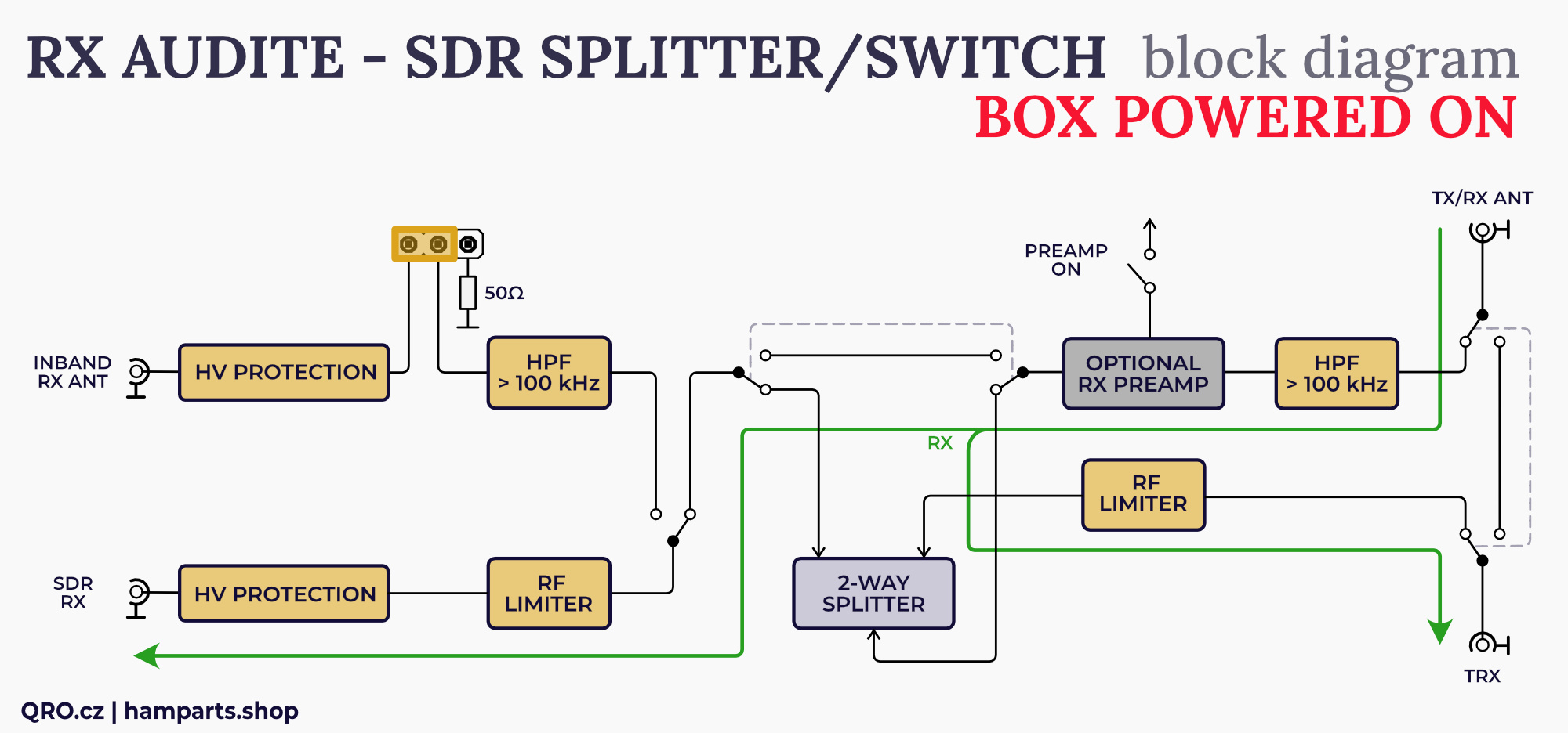
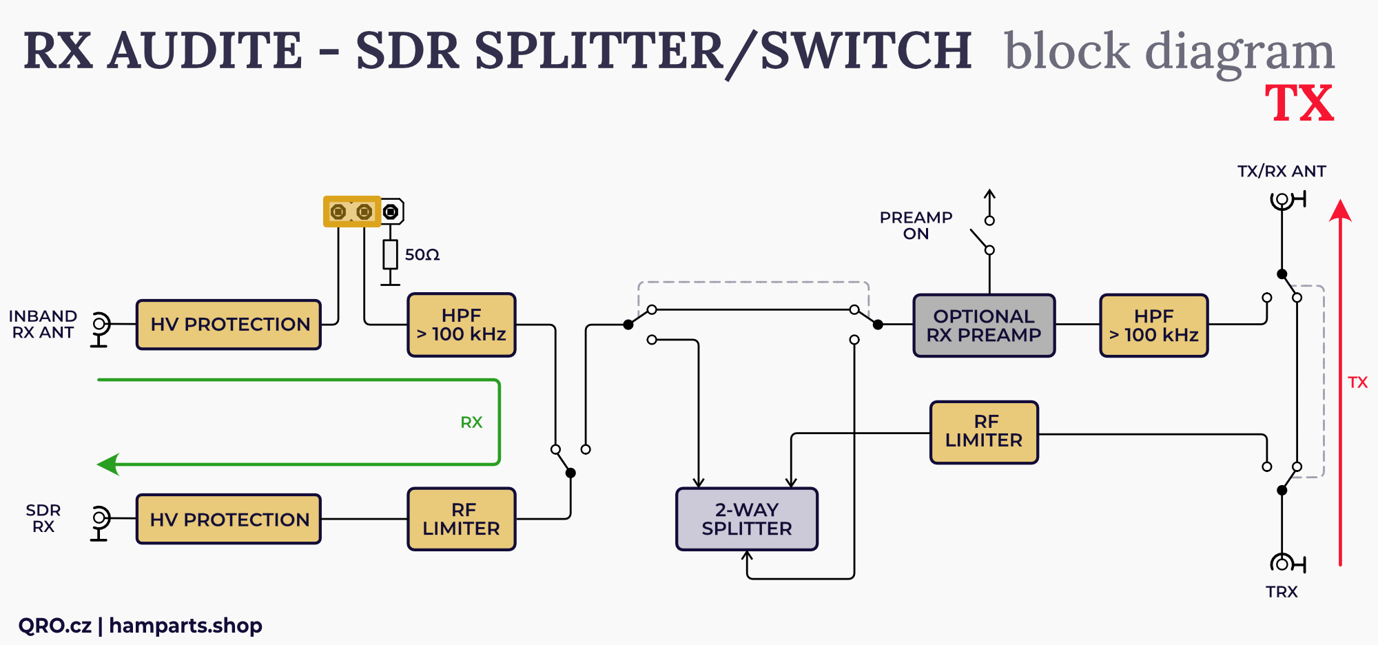
There is simply blog diagram of the controller. RX lines have got high voltage and current protection, High Pass Filter (100 kHz), 2-way RX splitter and optional RX preamplifier. You can see functions at the pictures below.
Block diagram
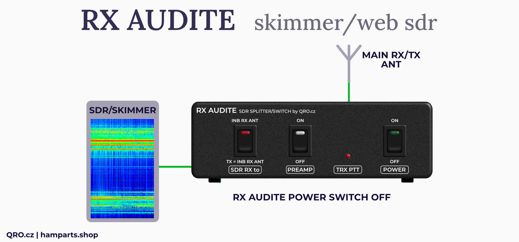
Controller is switched OFF
Even the Power Switch is OFF, you are able to switch ON the internal Preamp - controller must be powered by the DC voltage
Signal from the main TX/RX ANT goes to the RX (SDR) output port. There are protection and RF limiter
Controller is switched ON
Signal from the main TX/RX ANT goes to the TRX and RX (SDR) output port via the 2-way splitter
There are protections and RF limiters for both outputs
You can use Preamplifier if it is built inside - if you have not the version with preamplifier, you can order the optional preamp module.
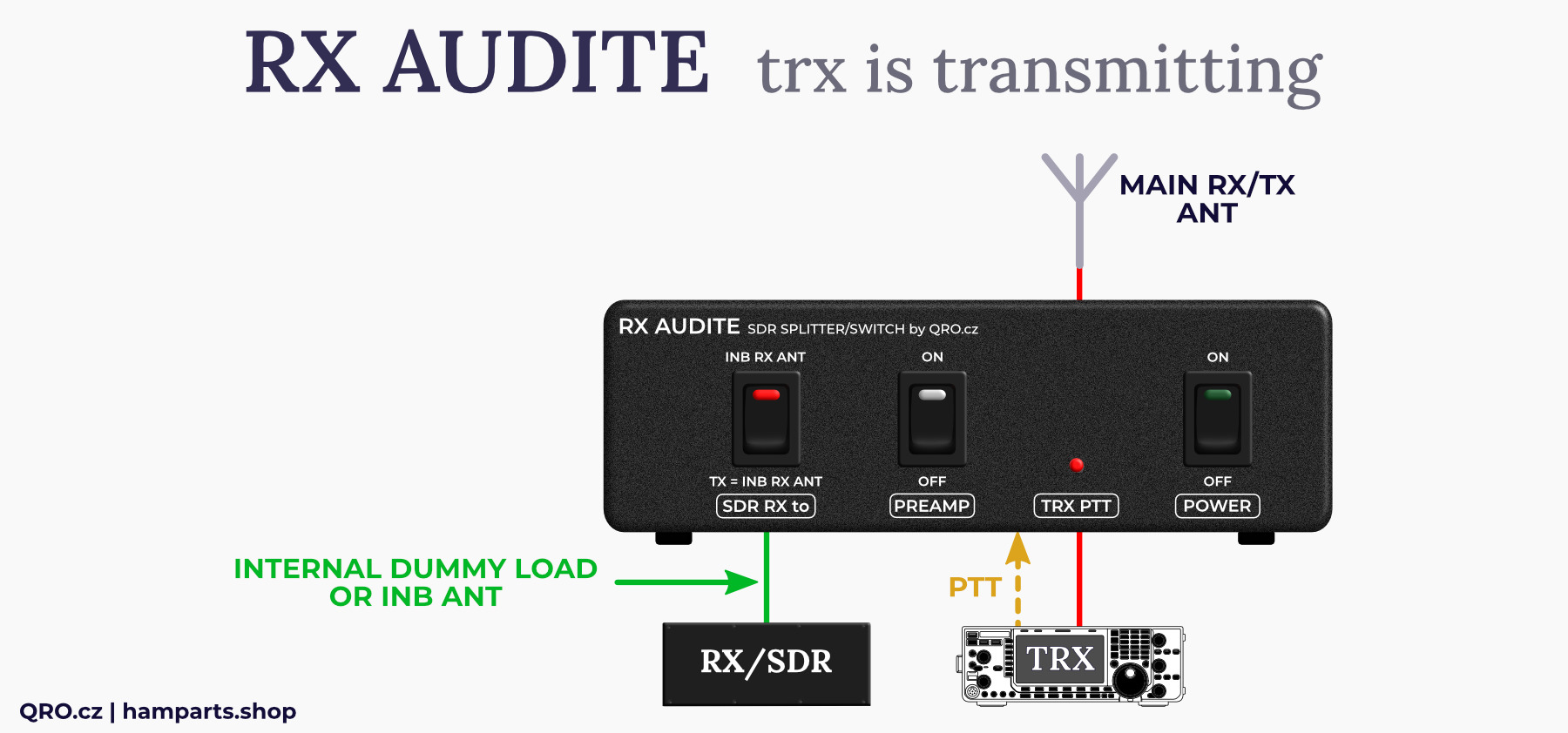
Controller is switched ON: TRX is transmitting
TRX is transmitting to the main TX/RX ANT and RX (SDR) output port is connected to the internal dummy load or to the INBAND RX ANT port
There are protections and RF limiter
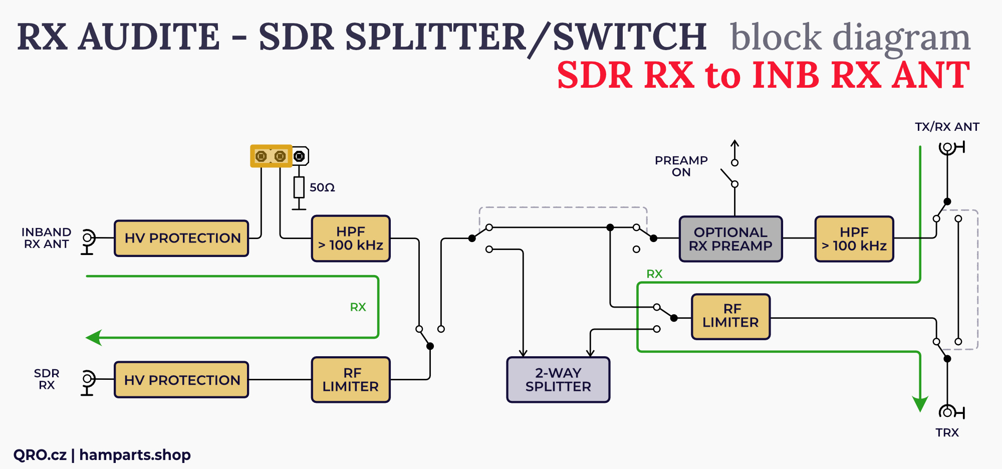
Controller is switched ON: RX (SDR) out switched to INBAND RX ANT by the front panel switch
In this case main TX/RX ANT goes to the TRX port via the protections and limiter and you can use also preamplifier
SDR RX output port is connected to INBAND RX ANT input
There are protections and RF limiter
Jumper settings
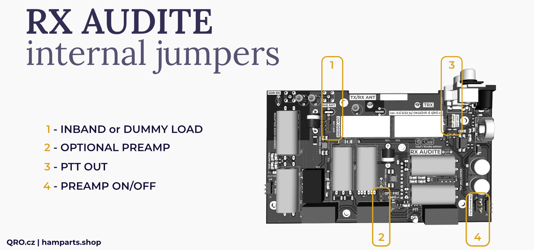
1. INBAND or DUMMY LOAD
SDR output could be connected to Inband RX antenna or internal 50 Ohm dummy load. When you do not use Inband RX antenna, please set this jumper to internal dummy load or connect external small dummy load to Inband SMA connector.
2. OPTIONAL PREAMP
- Remove this jumper when the optional preamp is installed
- Must be shorted while there is no preamp module
MK3 version has got Preamp installed and there is no jumper for this (SN: 2506xxx and higher)
3. PTT OUT
- Selecting between sniffer mode and PTT FET
- Please, see next picture with an explanation
4. PREAM ON/OFF
This jumper allows you to switch preamp only while the controller box is ON (main power switch is ON) or you can switch preamp independently on main power ON switch and use preamp also while the controller is OFF (this is in case you want to have preamp for SDR all time ON).
RF limiter
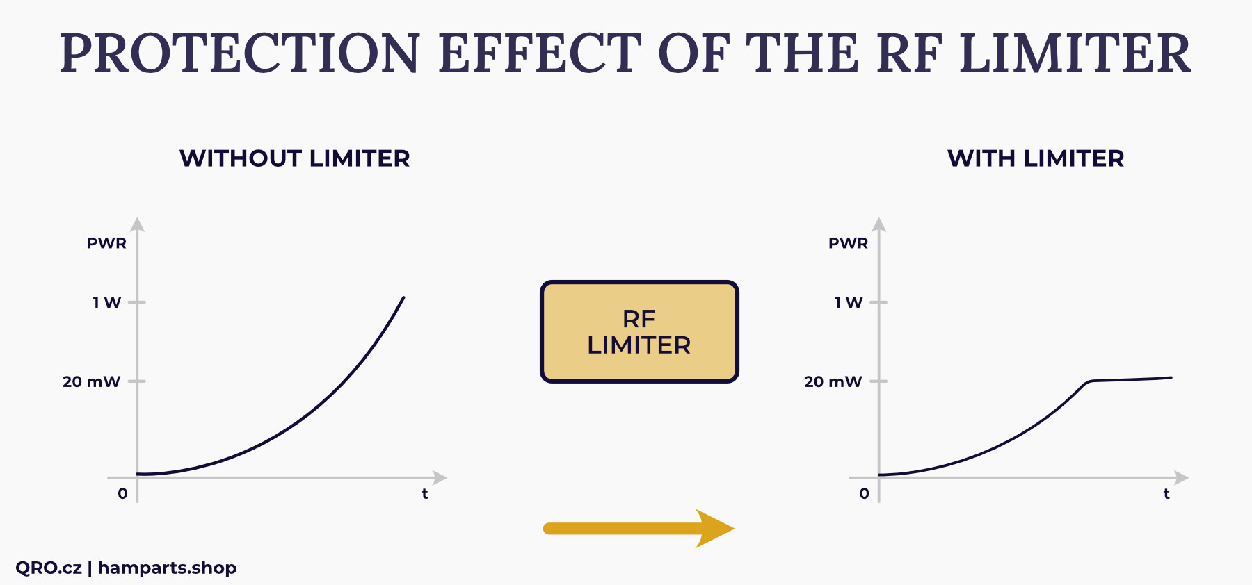
The RF limiter is a unique device that can save you a lot of money on damaged receivers. Its design is based on proven circuits that do not affect IMD. When combined with SuperFuse, it provides enhanced protection.
The principle behind the limiter is simple. It is based on fast anti-parallel diodes. These are placed in isolation between two transformers. This improves the edges during limiting, thereby reducing harmonic signals and intermodulation distortion (IMD). When used with SupeFuse, the circuit is interrupted when the current exceeds 100 mA. This function protects the limiter itself and also provides additional reversible protection in the event of a very high signal level, such as 10–100 W RF.
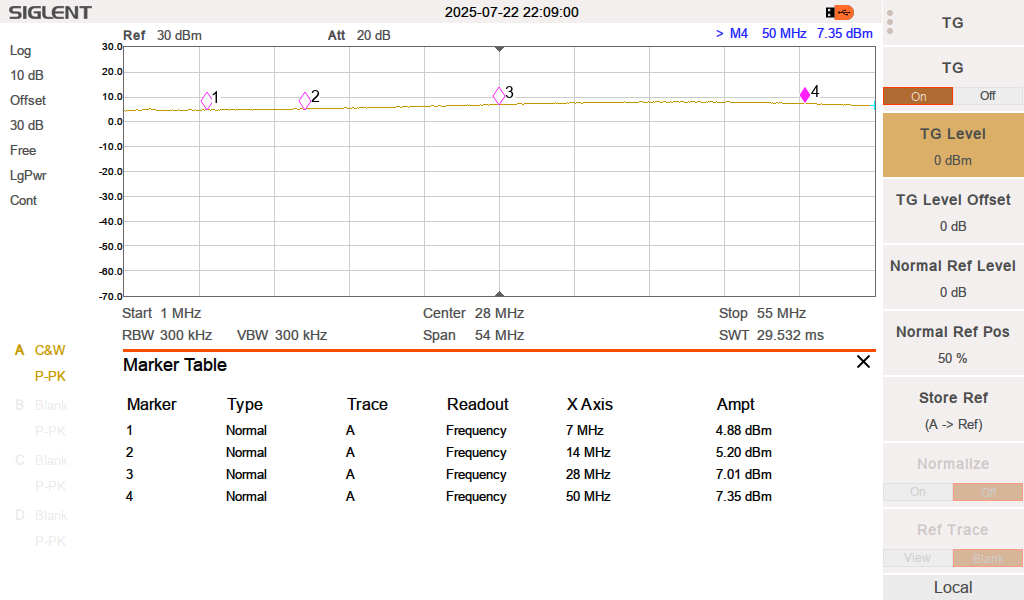
The figure shows an example of a limitation at 13 dBm (20 mW)
Examples of MK3 version measurements with 30 dBm = 1 W RF signal at antenna inputs. These measured signals are at the output port for RX (as described in the figures).
Main ANT to TRX port (splitter ON)
Main ANT to RX (SDR) port (splitter ON)
Main ANT to RX (SDR) port and PREAMP ON (splitter ON)
INB ANT to RX (SDR) port
Own TX signal at SDR out
The RX Audite offers high isolation between the SDR RX output and the TRX during transmission. This isolation protects the SDR from destruction or damage. However, physics is mathematically determined. If the SDR also has its own LNA (preamplifier), it can indicate a very strong signal. Here is an example with a calculation:
Let's assume isolation when the RX (SDR) output is connected to an internal dummy load:
Isolation 100 dB (typ. 110 dB for MK3)
Transmission signal 100 W = 50 dBm
If we ignore other losses, the signal level on the SDR will be 50 dBm – 100 dB = - 50 dBm
!! If we use an external INB ANT, the isolation will also depend on the isolation between the TX antenna and the antenna in the INB ANT port!
If the SDR does not have its own preamplifier (PRE, LNA), then it should show its own signal at a level of approximately -50 dBm.
dBm to S unit level:
-50 dBm = S9 + 25 dB
-43 dBm = S9 + 30 dB
-33 dBm = S9 + 40 dB etc.
Measurements
There you will find measurements of RF parameters for the RX Audite version MK3 (2025).
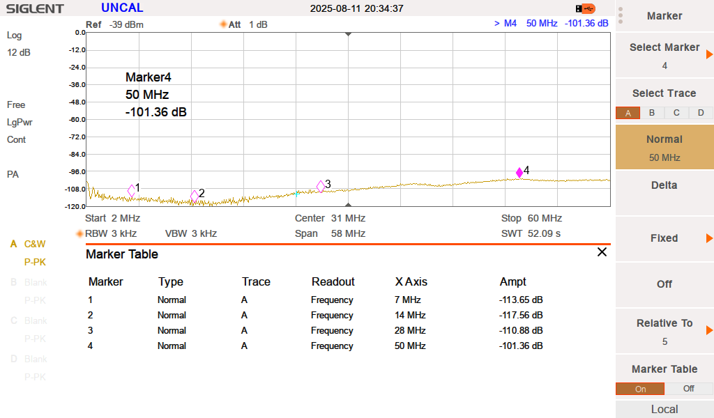
Isolation while transmitting. Own signal to RX (SDR) out
An important parameter of isolation between the transmitter and the second RX (SDR) output. There 110 dB means 1 nW of RF power at this RX output from 100 W of transmitted signal.
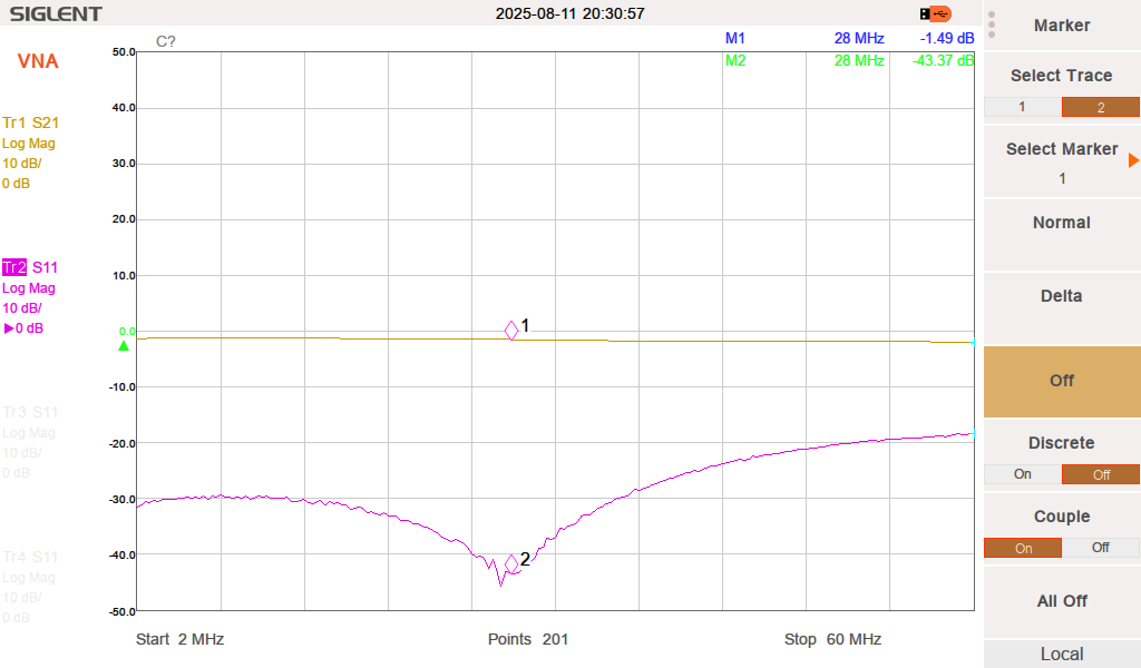
RXA OFF, Main TX/RX ANT to RX (SDR) output, PREAMP OFF
This is for the RXA turned off, when the signal passes from the main antenna to the RX (SDR) output. The PREAMP is turned off and there are several protections including an RF limiter. The pass-through attenuation is typically 1.5 dB.
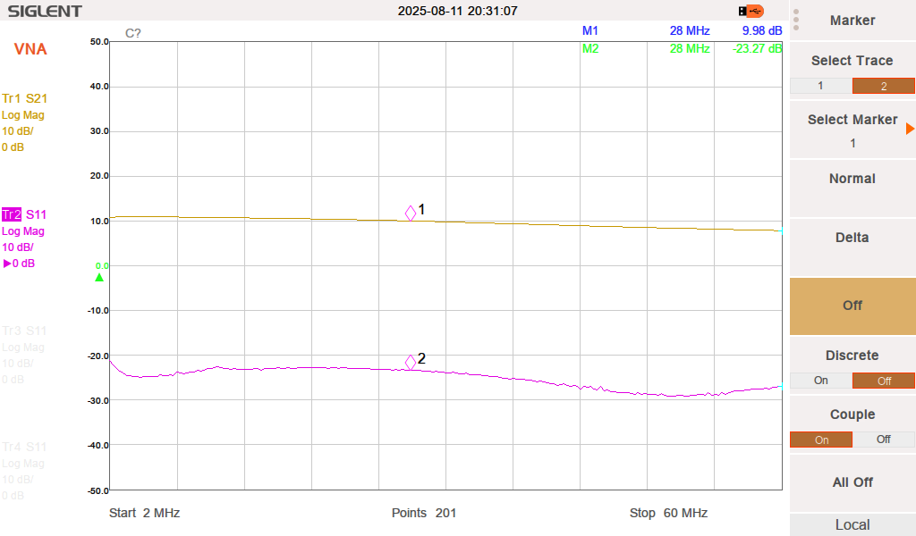
RXA OFF, Main TX/RX ANT to RX (SDR) output, PREAMP ON
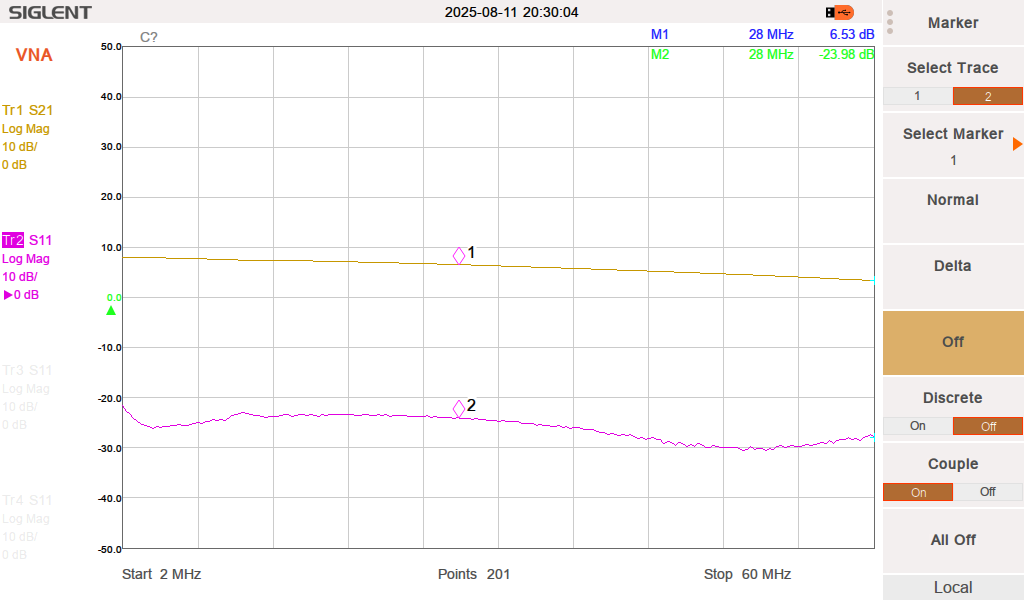
The same measurements but with the PREAMP ON. You can see pre-set gain to typ. 10 dB.
Main TX/RX ANT to TRX and RX (SDR) output, PREAMP ON. Measured at TRX port
Main antenna shared to two receivers. There are all protections in path and PREAMP on. There is additional 6 dB of gain pre-set (1 S unit).
Previous versions
ℹ Manual for previous versions: manual


.png)
-SDR.png)
-SDR-PREAMP_ON.png)
