Variable HP Attenuator manual
This high power attenuator is passive device converting RF power to heat. There you can find more information and examples how to use it. This is not high precision device but it can handle higher power and you can switch by 0.5 dB steps. It is ideal for power amplifier input power changing in steps.
Jump to
Applications
Attenuator
Parameters
Schematic
PCB
Product details
Applications
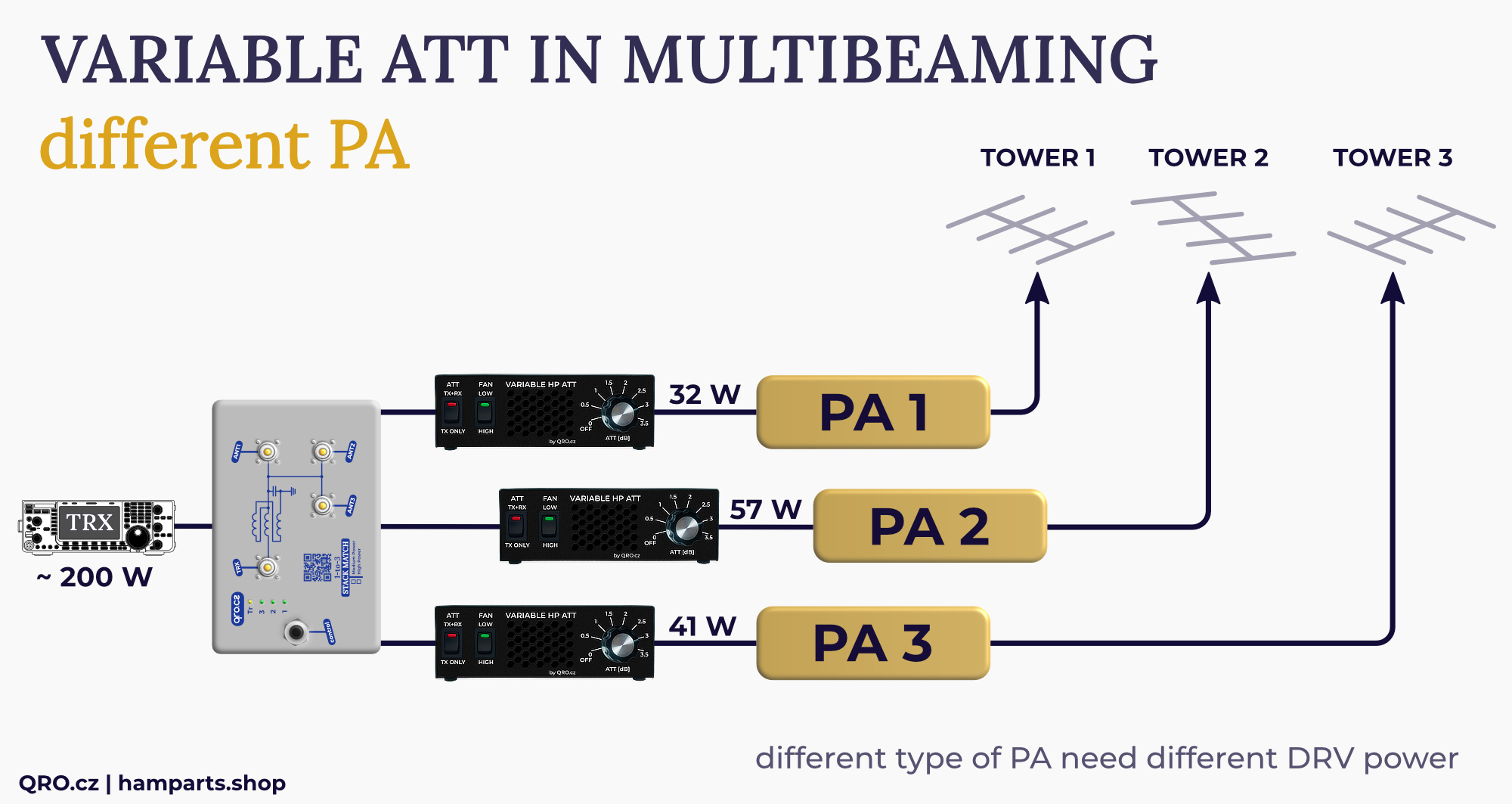
Example of the multibeaming with three different PA
- splitting the power by stack match
- three different drive powers to PA with three variable ATT (attenuator)
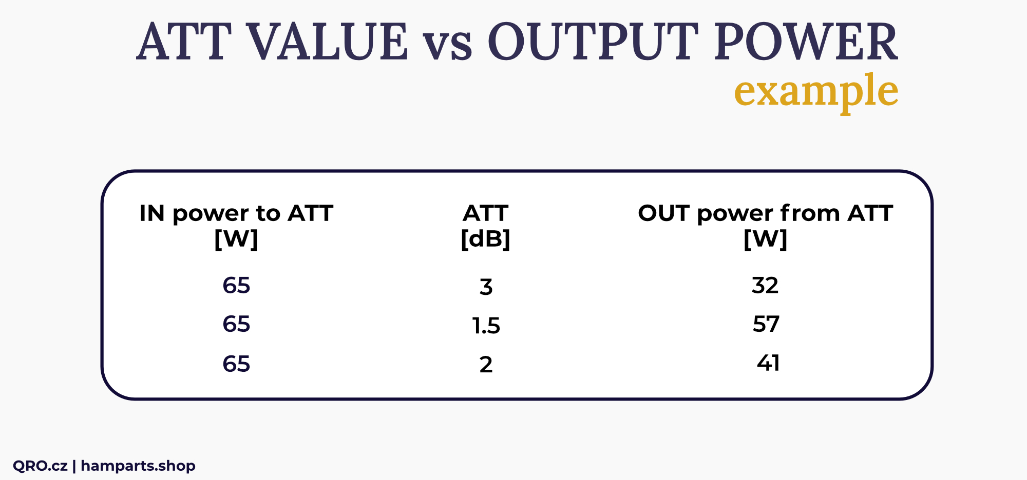
Example of output power with different ATT value
- for 100W input
- without insertion loss (IL)
Attenuator
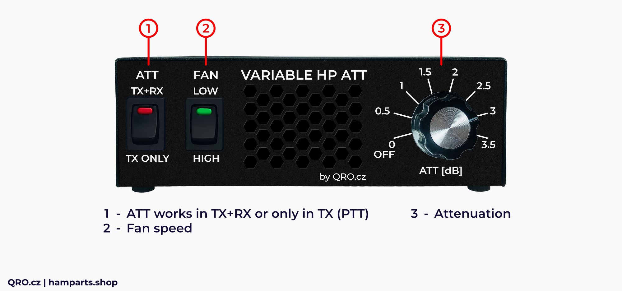
1. When is the ATT connected to the RF line
- switch in position TX+RX: ATT is connected alway (PTT is not required)
- switch in position TX: ATT is connected only with PTT (low), RX = bypass
2. FAN speed
- predefined two fan speeds
- automatic fan speed increase when the PCB is overheated
3. ATT switch
- attenuation in steps by 0.5 dB
Parameters
- Input power CW/SSB and RTTY: 250 W/150 W PEP in DX mode & 150 W/100 W in contest mode
- Fan speed control
- Frequency range: DC to 30 MHz
- Worst SWR (30 MHz) 1:1.2
- Maximal sloping 1 to 30 MHz: 0.5 dB
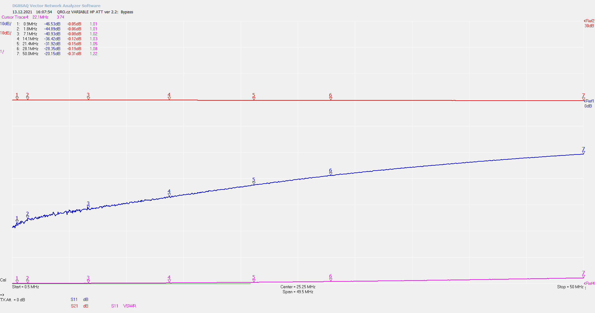
ATT BYPASS 0 dB
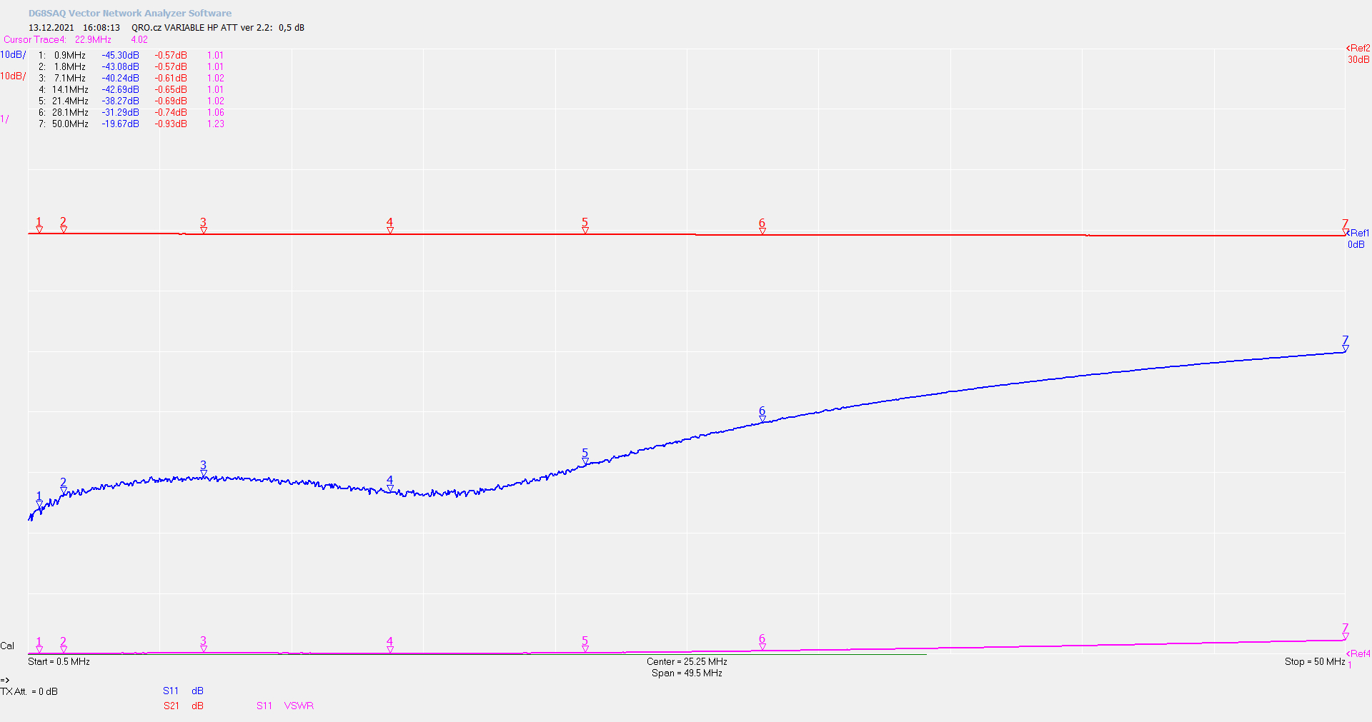
ATT 0.5 dB
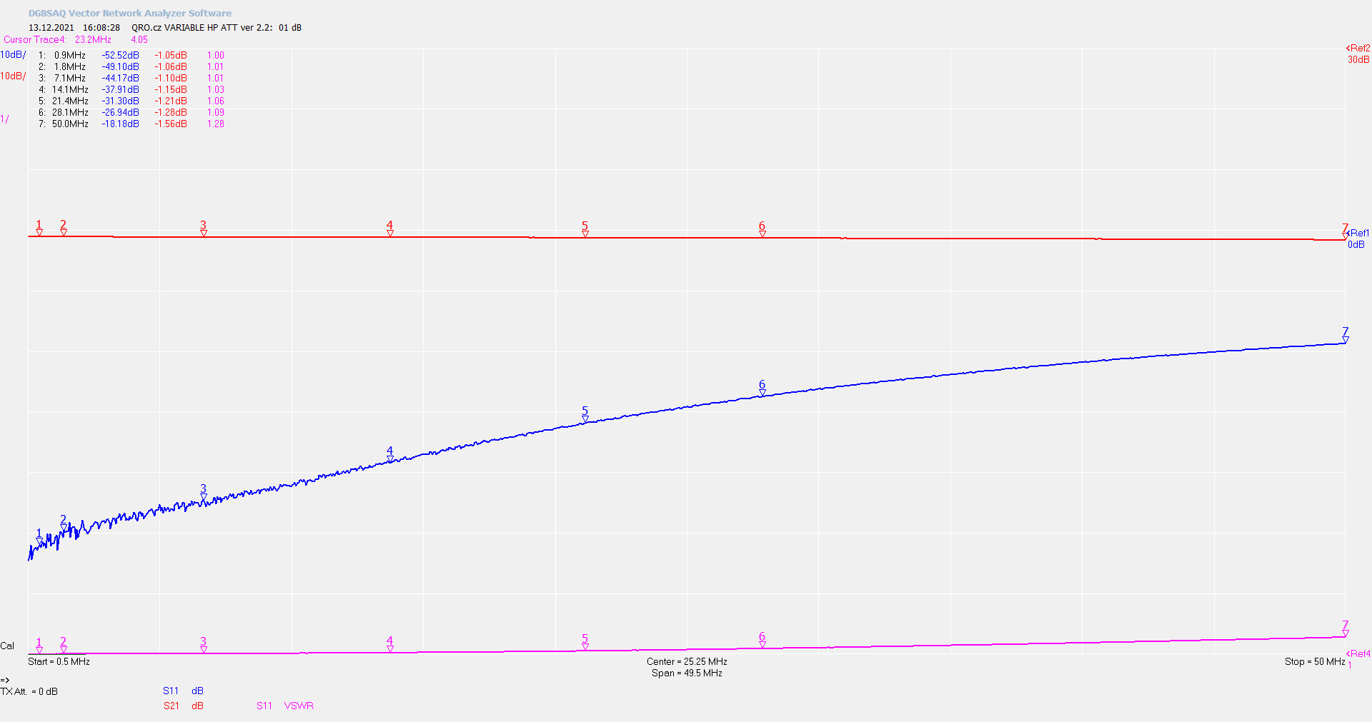
ATT 1 dB
ATT 1.5 dB
ATT 2 dB
ATT 2.5 dB
ATT 3 dB
ATT 3.5 dB

