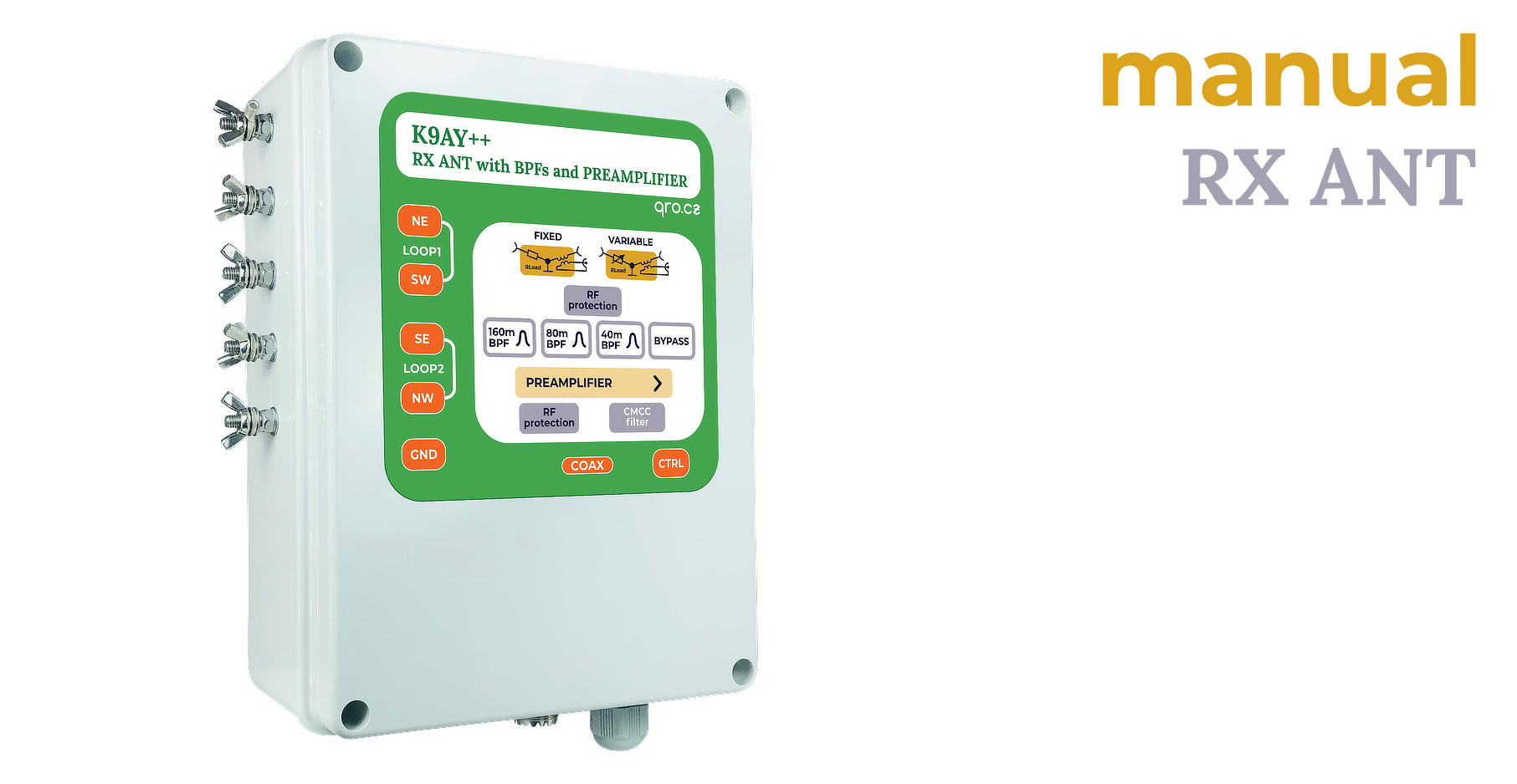
This manual page is for a few versions of the controllers - there are information also for older versions. One version is for K9AY++ antenna and the second for K9AY/4-way Beverage system. There were classic and remote controller version. Now, new MK2 (since 2025) is only with REMOTE input.
Controller offers:
- Direction knob switch
- Direction LED indication (4 directions)
- Manual/Remote control LED
- Rload voltage knob
- BPF + ByPass switch
- Preamp control and RX source switch
- PTT hot switch and splitter
- RF protections
K9AY/4-way antenna switch allows you to control:
Jump to
Front panel description
Rear panel description
Controller comparison & block diagrams
Controller to TRX connection
example 1 TRX with RX ANT input
example 2 TRX with RX ANT in and out
example 3 ALL TRX - universal configuration
Connectors description
Remote Controllers
Application
PTT information
4-WAY/K9AY external switch
Variable Rload resistance
Jumpers settings
Internal BPF and Preamp board
Product details
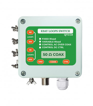
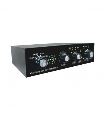
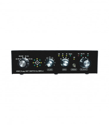
Front panel description
There are rotary switches, LED indicators and one small switch
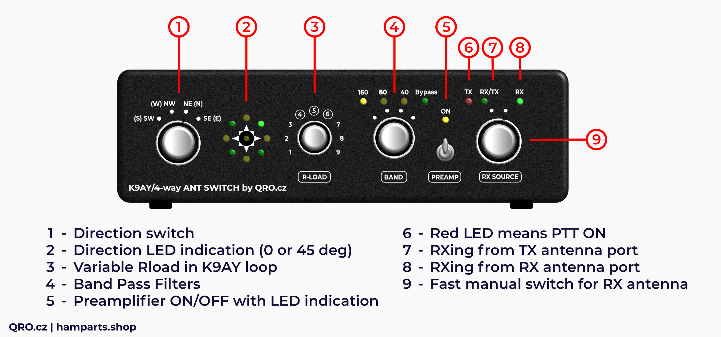
1. Direction switch
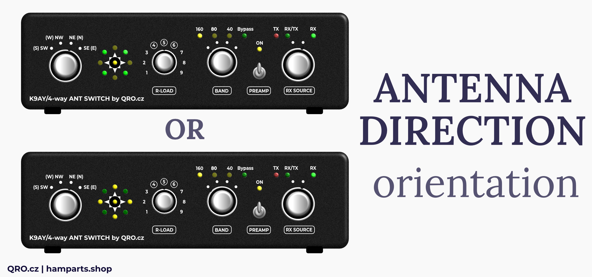
- There are two possible ways how to build antenna
- Loops can be mounted in N-S-W-E or NW-SE-NE-SW orientation
2. Direction LED indication
- Direction LED indicators can work in N-S-W-E or NW-SE-NE-SW
- Please, have a look at jumpers settings
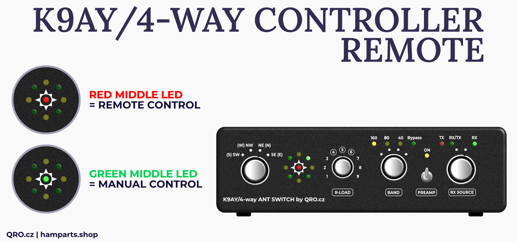
- middle LED shows manual/remote control for Remote version of the controller
3. Variable Rload in K9AY loop
- This knob allows you to change Load (terminate) resistance
- You have to have right jumpers settings and you are able to set maximal resistance and also resistance in the middle (5) of the knob
- Terminal resistance of the loops - from about 200 to 1200 Ohms
- Please, have a look at trimmers settings
4. Band Pass Filter
- Knob for BPF of Bypass selecting
5. Preamplifier
- Preamplifier On/Off switch and LED indicator
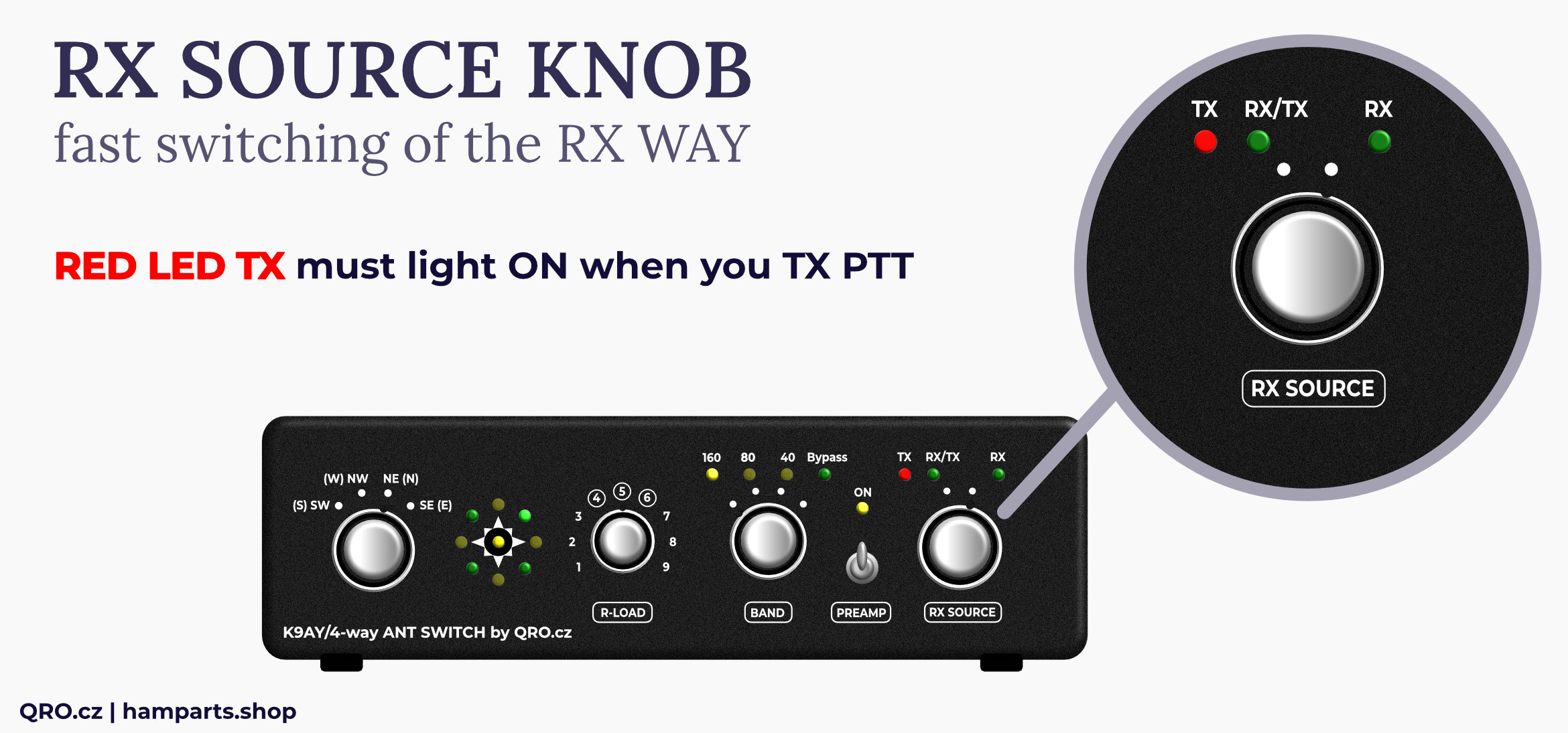
6. TX LED
- PTT LED indicator
- Please, read more in this manual
7. RX/TX
- This LED indicates RX from your TX antenna
8. RX
- This LED indicates RX from RX antenna port
9. Fast manual switch for RX antenna
- You can use this knob for fast switching between TX and RX antennas
- This is good feature for TRX without RX ANT input port
- Please, have a look at more in this manual - there is more way how to use/connect it
Middle LED shows manual or remote control status (in the case of remote control version)
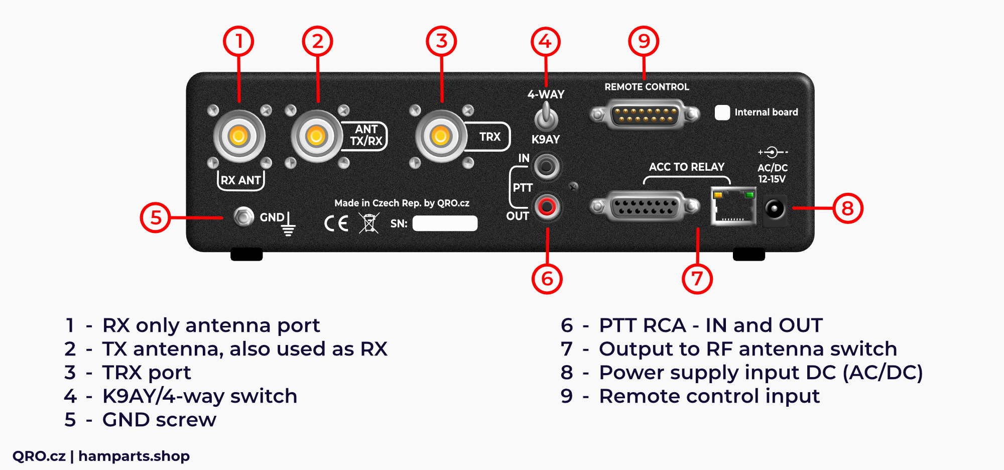
Rear panel description
Rear panels are almost the same for manual and remote controller version. There are connectors and small switch between K9AY and 4-WAY antenna system.
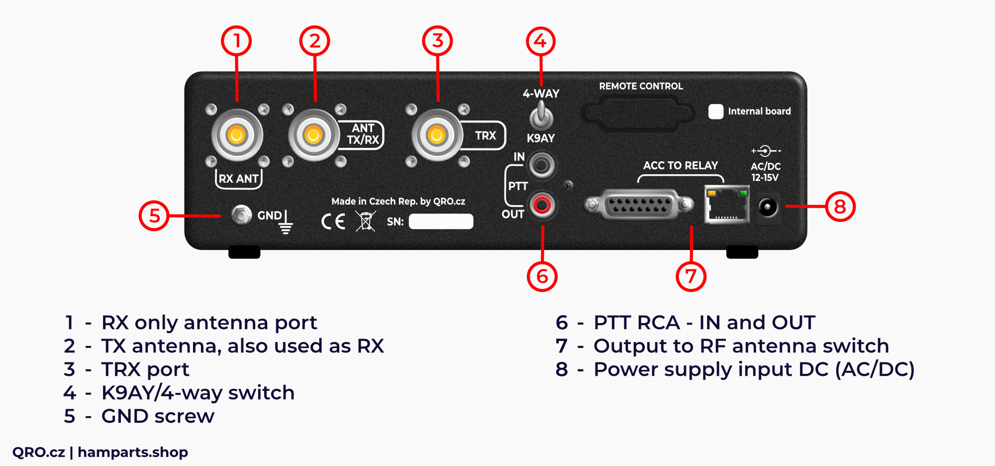
1. RX ANT
- Input connector for the RX ANTENNA
- There is Bias Tee, RF and HV protections and diode RF limiter
2. ANT TX/RX
- RF port for TX antenna
- There is more ways how to connect controller to TRX
- This port can be used for TX antenna and you can use from panel switch for fast selecting of the RX source
3. TRX
- TRX or RX port
- Depends on your connection
4. K9AY/4-WAY switch
- This controller allows to control K9AY and 4-WAY Bi-dir Beverage system
- There are different matrix tables for direction switching - one for K9AY (DC voltage over the ACC connectors and AC/DC voltage over the coax cable) and 4-WAY system (AC/DC voltage over the coax for 4 directions)
5. GND screw
- It is highly recommended to connect controller to the common ground in the hamshack
- There are high voltage protections in the controller which needs ground to discharge any potential high voltage
6. PTT RCA
- PTT signal controls RX source switch
- This depends on your configuration but if you use controller also in TX RF line, you have to connect PTT from TRX (keyed)
- PTT signal connects TRX to TX/RX ANT port when you are transmitting
- PTT works in the sniffer mode
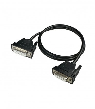
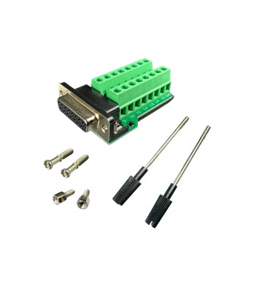
7. Connectors to RF switch
- There are two connectors - DB15F and RJ-45
- It is almost the same, please have a look at the connector description
- Both ports have got high voltage protections and basic RFI filters
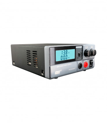
8. Power supply input jack
- Power supply input jack 5.5x2.1 mm
- You can use +12 to +15V DC in the case of K9AY++ antenna system
- Controller for 4-WAY Beverage system needs AC power supply
- The directional switching is made by + DC, - DC, AC and 0V
- There is high quality common-mode filter to eliminate any RFI and AC noise from power supply
9. Remote Control connector
- Only in Remote version of the controllers
- Please, have a look at the connector description in this manual
Controller comparison & block diagrams
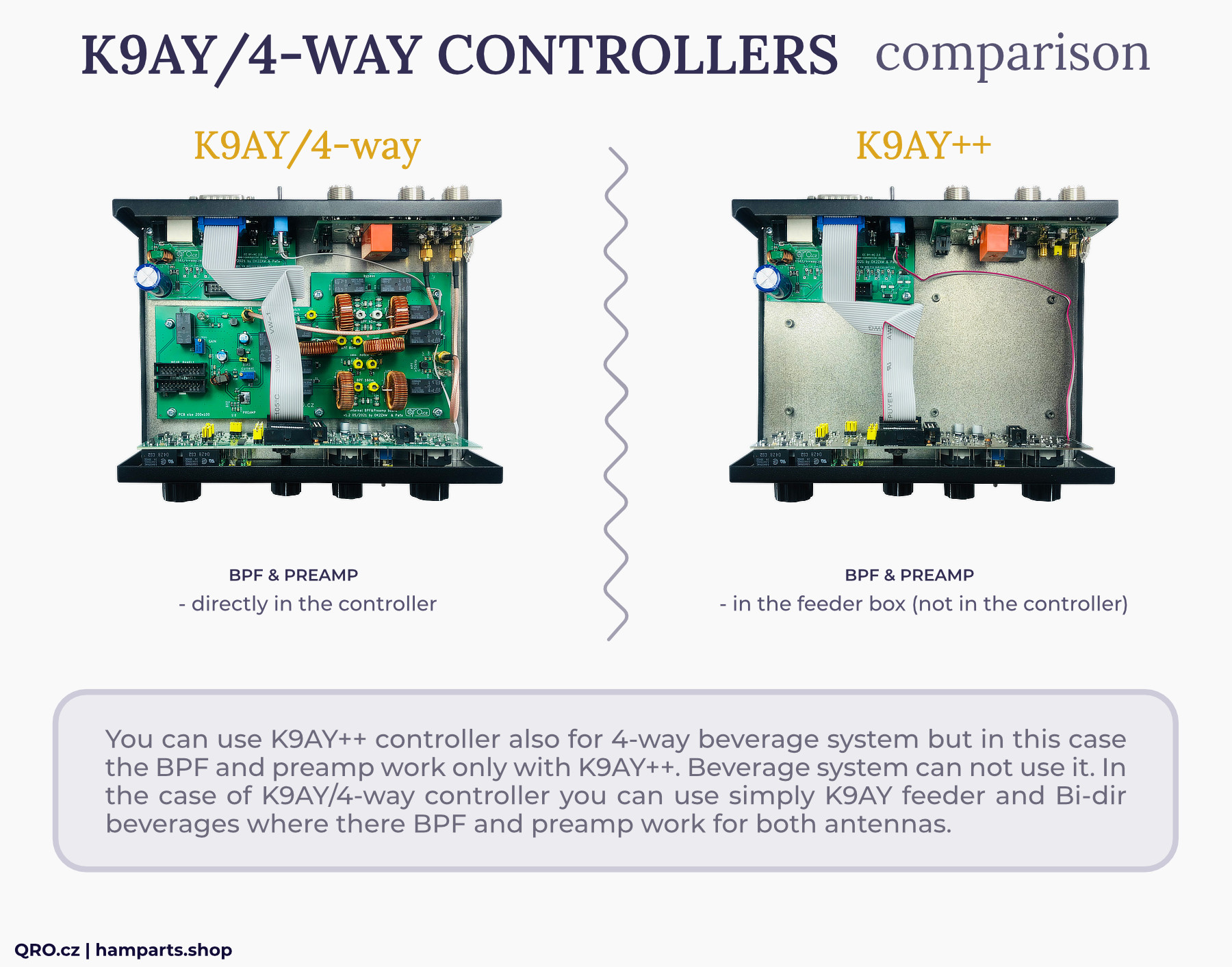
The difference between K9AY++ controller and K9AY/4-WAY is in the internal BPF and PREAMP board:
- K9AY++ system has got BPF and preamp in the feeder box
- K9AY/4-way controller has got it directly in the controller
You can use K9AY++ controller also for 4-way Beverage system but in this case the BPF and preamp work only with K9AY++.
Beverage system cannot use it. In the case of K9AY/4-way controller you can use simply K9AY feeder and Bi-dir Beverages where there BPF and preamp work for both antennas.
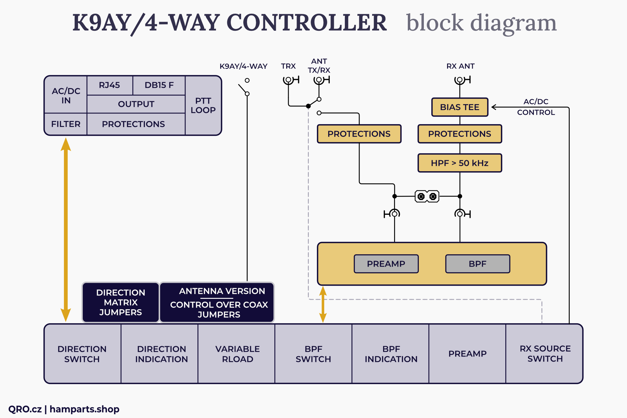
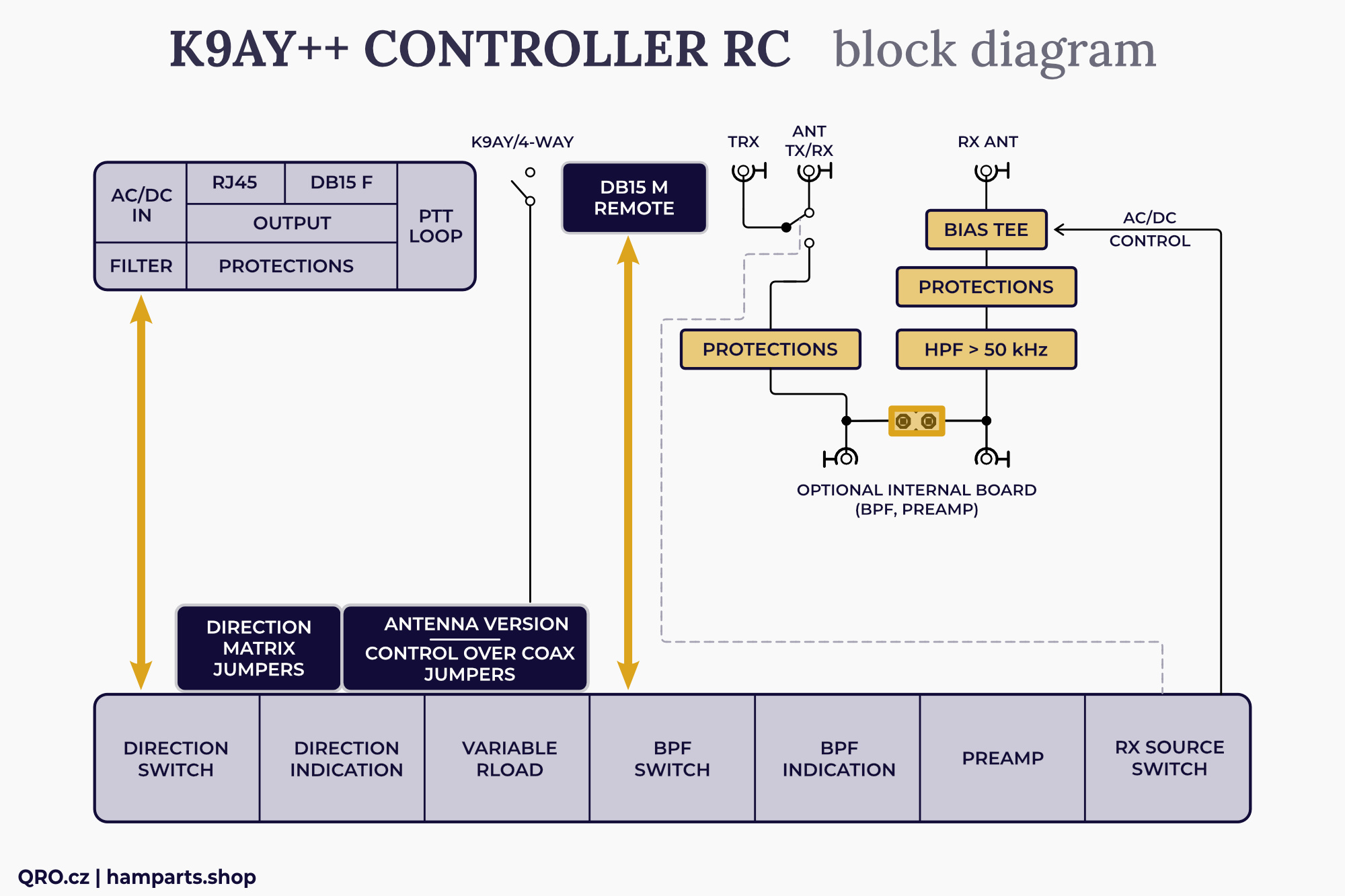
Block diagrams of the all controller versions
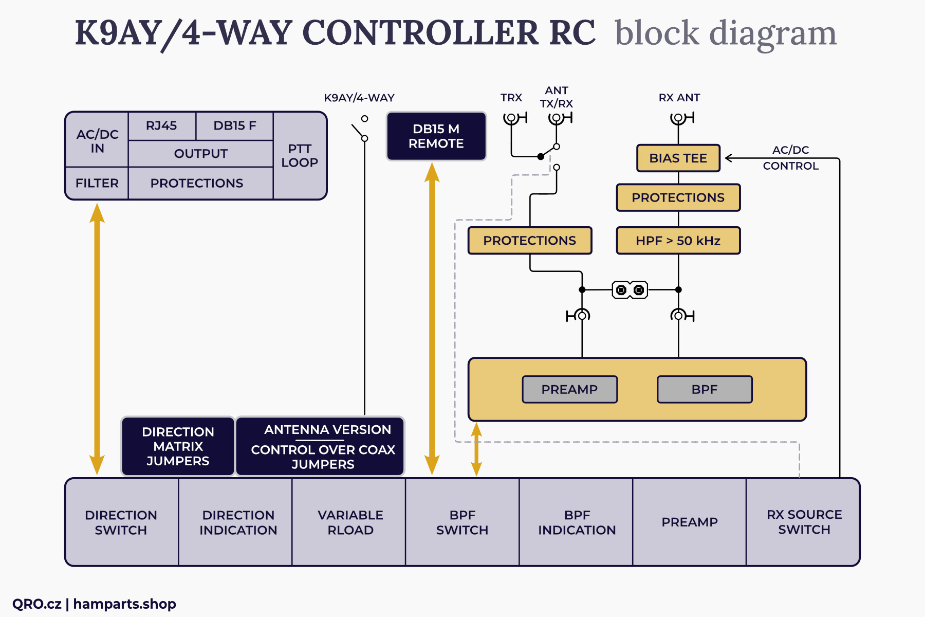
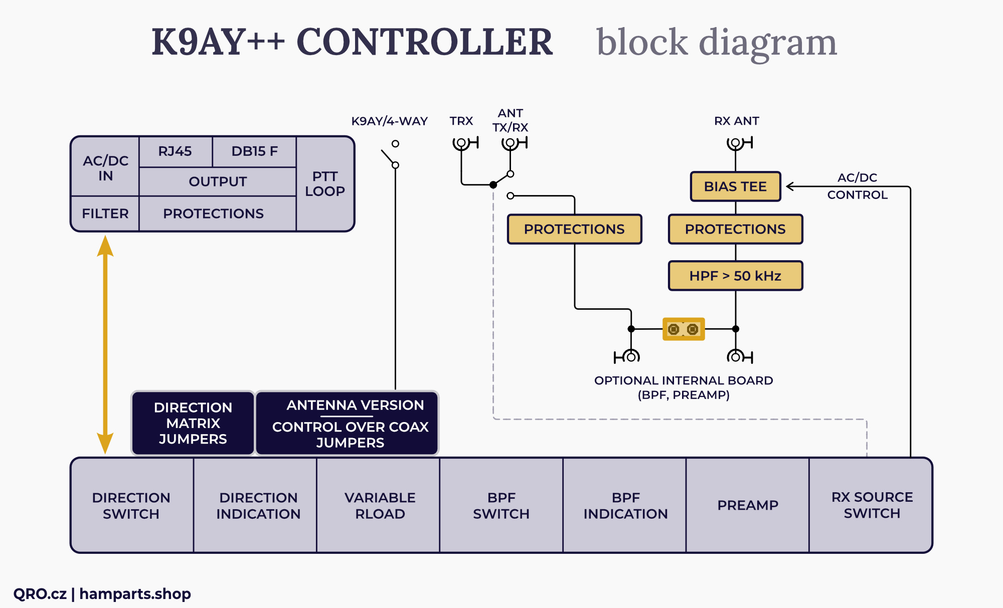
There are four block diagrams. The first two pictures are description of K9AY/4-WAY controller with Internal BPF and Preamp board. Another two pictures are for K9AY++ controller. Second and fourth pictures have got added Remote Connector.
New MK2 version (2025) is only with Remote input. There are still two version with and without Preamp and BPF internal board. Controller without this board is included in K9AY++ set.
Block diagram for K9AY/4-WAY controller with Internal board
Block diagram for K9AY/4-WAY controller (remote version) with Internal board
Block diagram for K9AY++ (4-WAY) controller without Internal board
Block diagram for K9AY++ (4-WAY) controller (remote version) without Internal board
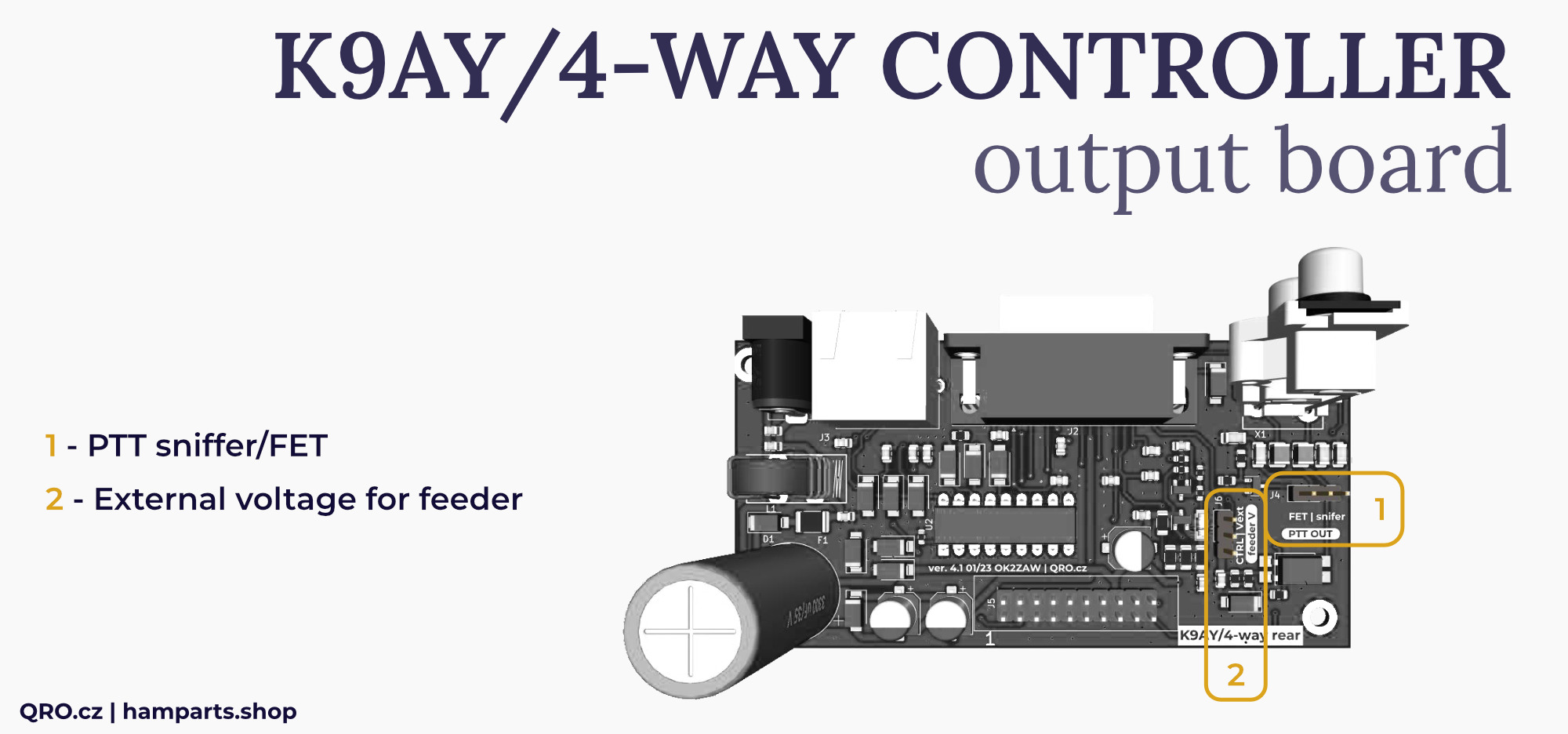
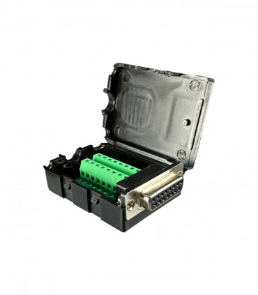
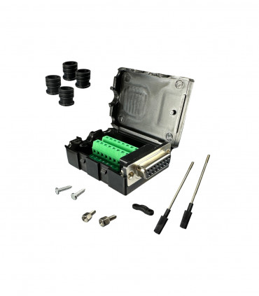
Rear output connectors board
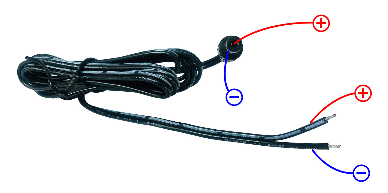
- DC (AC/DC) connector with common-mode current filter, PTC resettable fuse protection and DC filtering
- PTT IN and OUT RCA connectors work in sniffer mode. It is compatible with > + 5V in open state of the PTT. PTT detects LOW for TX. There is also PTT OUT FET option in the controllers 3/2022 and newer. PTT input has optocoupler as isolation for rest parts in controller.
- Output connectors (RJ45 and DB-15M) are almost the same. Outputs to external boxes - like K9AY++ feeder. Please, have a look at connectors descriptions in this manual. There are also high voltage protections and RFI filters.
Front panel board
- There are two different versions of the front panels. One for the classic version and the second for remote controlled one
- There is also a couple of the jumpers - please, have a look at the jumpers descriptions
- You can change LED direction orientation, 4-way Beverage orientation, use AC voltage over the coax for K9AY simply antenna etc.
- Rload controller for terminal resistance of the loops - from about 200 to 1200 Ohms. Please, have a look at trimmers setting
- Switch for Band Pass Filters
- RX source switch - allows you to select antenna for your RX (TX or RX antenna). This is good feature for TRX without RX ANT input port. Please, have a look at more info in the manual - there is more way how to use/connect it.
This is ideal solution for small TRX as IC-7300, FT-DX10 and others without RX ANT input.
Rear RF switch board
- There is more way how to connect controller to your TRX - please check that part of the manual
- This board allows you to use this controller also in TX way.
- RX ANT port has got HPF (100 kHz) and high voltage and current protections. Including diode RF limit. In the case of TX you have to use PTT signal from your TRX (keyer).
- There is built-in Bias Tee for AC/DC voltage. RF single goes to 100 kHz HPF to eliminate AC noise
- There are two SMA connectors for internal BPF/preamp board. This board is there in the case of K9AY/4-WAY controller. K9AY++ controller does not have this internal board
Remote control
- Controller with Remote Control has got one more DB15 male connector. Please, have a look at connector description in this manual
Controller to TRX connection
There are three possible ways how to connect controller to your TRX. Please, have a look at next examples.
⚠ When the controller is OFF (no power supply voltage) then signal from TRX goes to TX/RX ANT port directly. PTT OUT does not work, when set to FET output.

RX SOURCE - fast switching for RX source between TX and RX inputs
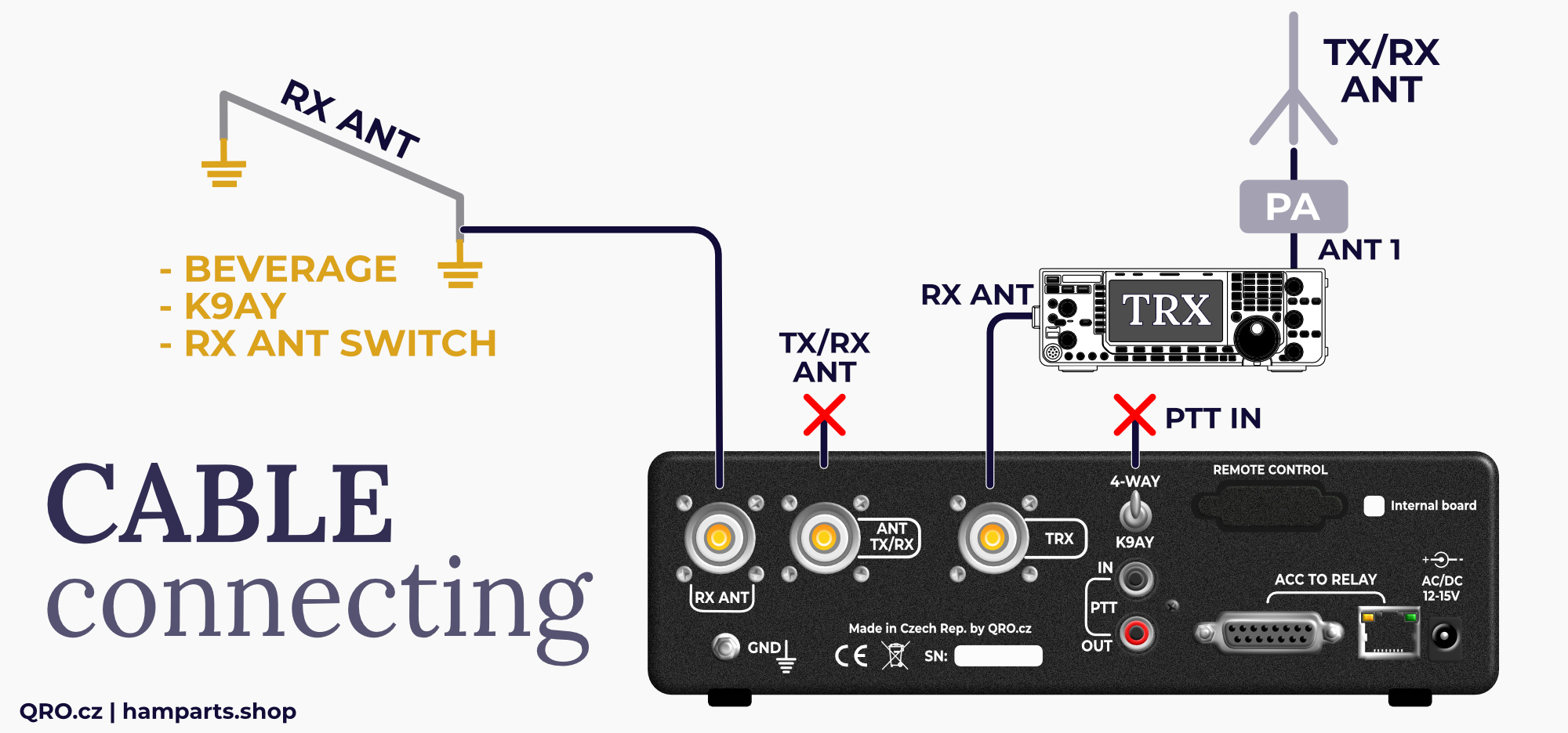
Example 1 - TRX with RX ANT input
- Does your TRX have RX ANT input? If yes, you can connect controller there. Then you do not need to connect PTT.
- Switching between TX and RX antennas for your receiver is done on your TRX by special button for RX ANT (check manual of your TRX)
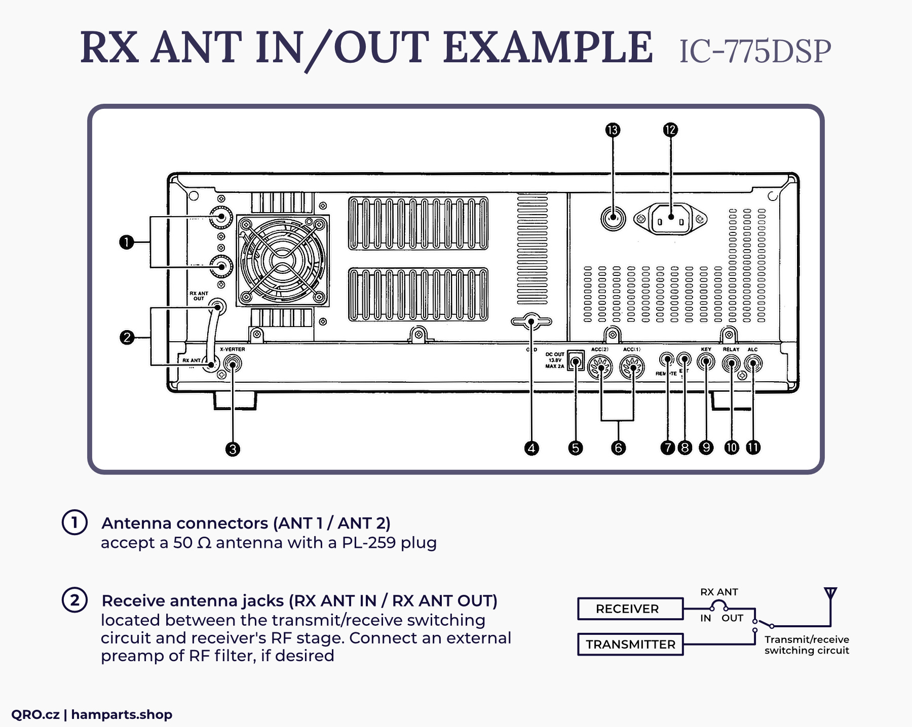
Example 2 - TRX with RX ANT in and out
- This example is only for TRX with RX ANT out and in connectors - like Icom IC-775, IC-7800, Yeas FT-1000 etc.
- Then you can use RX SOURCE switch on controller and do switching between RX and TX antenna. But you do not connect PTT to controller.
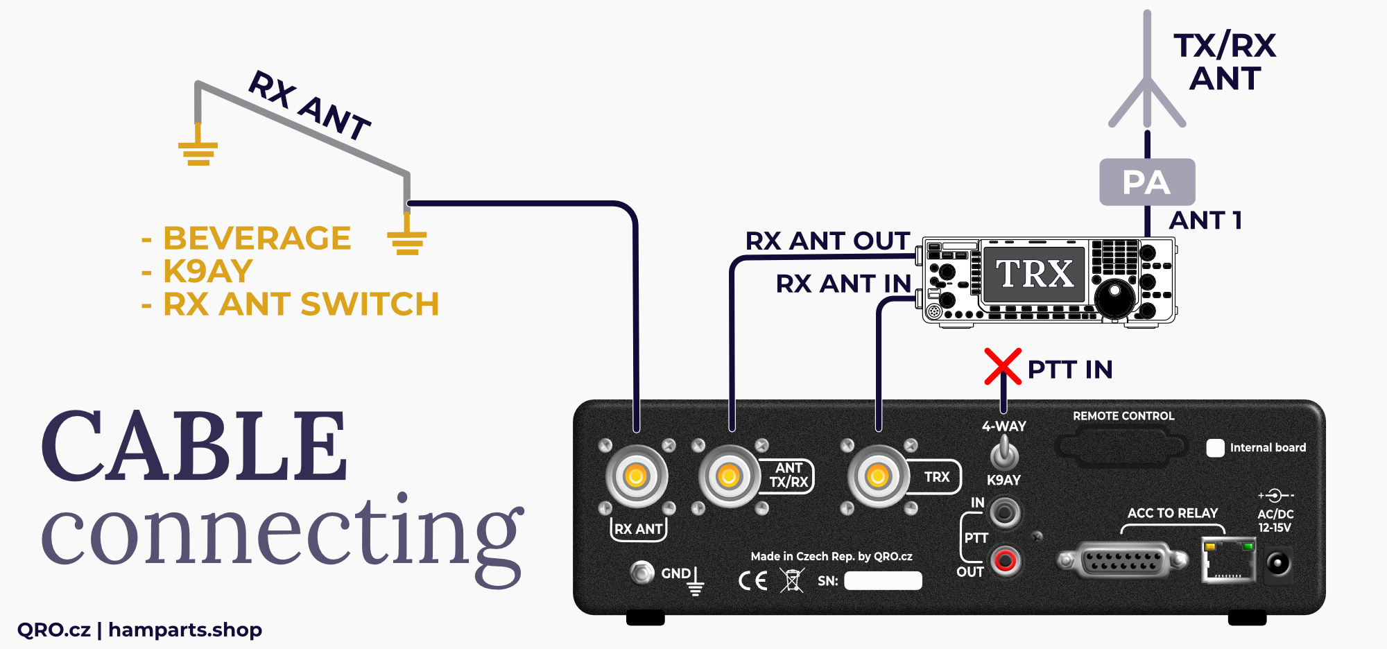
TRX example with RX ANT IN and OUT - there for IC-775 point 2
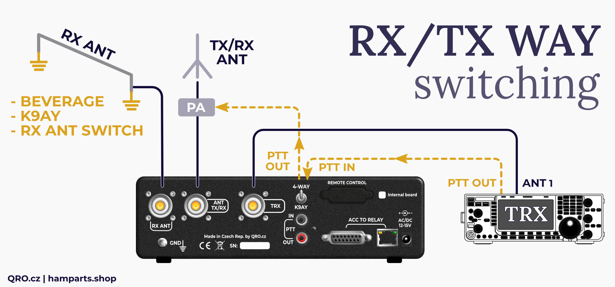
Example 3 - ALL TRX - universal configuration
- This is configuration for any TRX. In this example the controller works as RX ANT input for your TRX.
- You have to connect PTT from TRX to controller. When you are transmitting, controller switches relay and TX signal from your TRX goes to TX/RX RF connector at the controller - to TX antenna or PA.
- While receiving, you can simply and quickly switch between RX and TX antenna by the RX SOURCE knob. You can connect PA PTT from PTT out at the controller. If you use any kind of keyed or sequence, please, check its manual for more information.
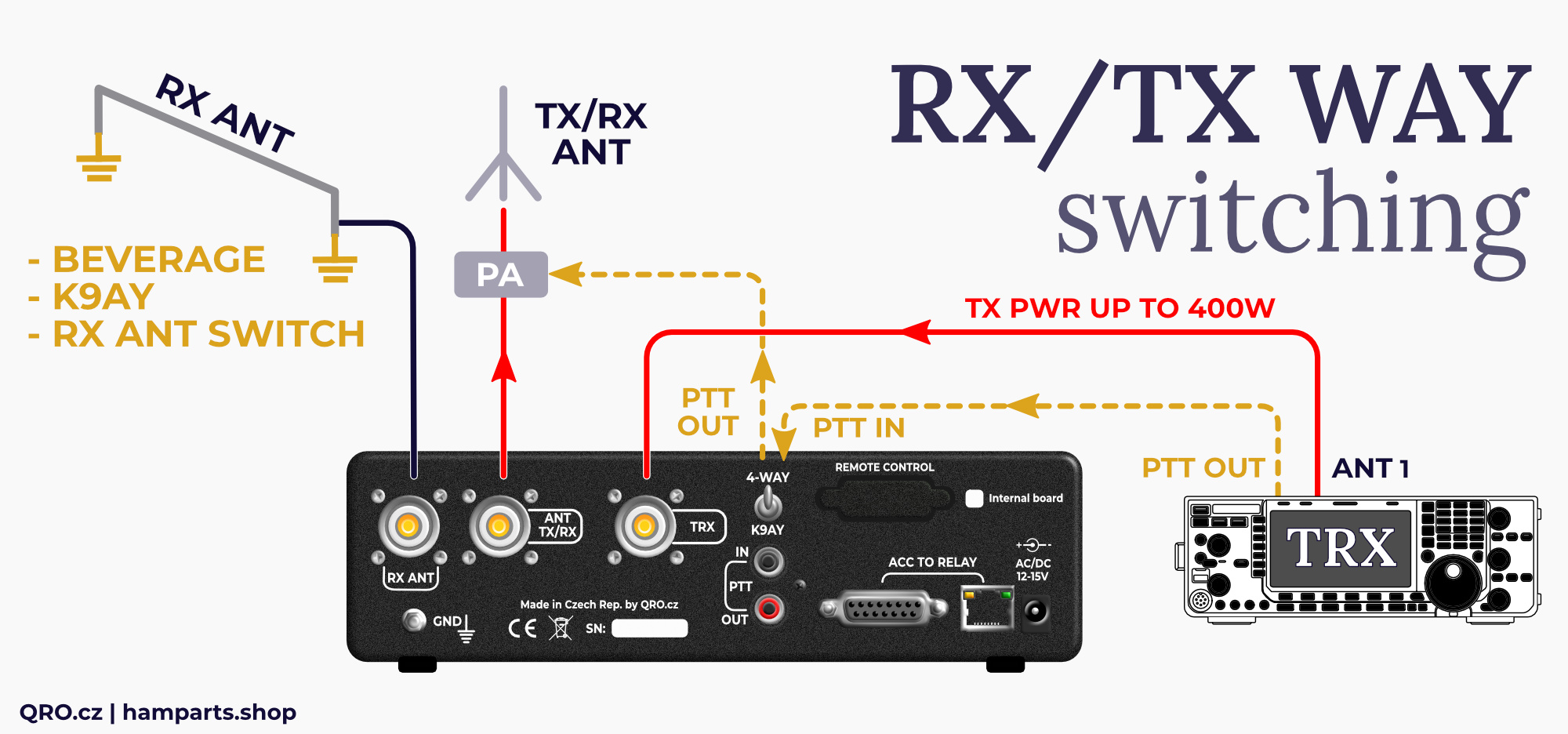
There the RED lines show TX signal way. Controller is able to handle up to 400 W. But low power level is recommended. If you use PA, please connect controller between TRX and PA. You can use controller from DC to 6m - when it is powered off from power supply or you can switch RX SOURCE knob to TX/RX on bands where you do not use RX antenna. Then controller works as simply bypass with minimal insertion loss.
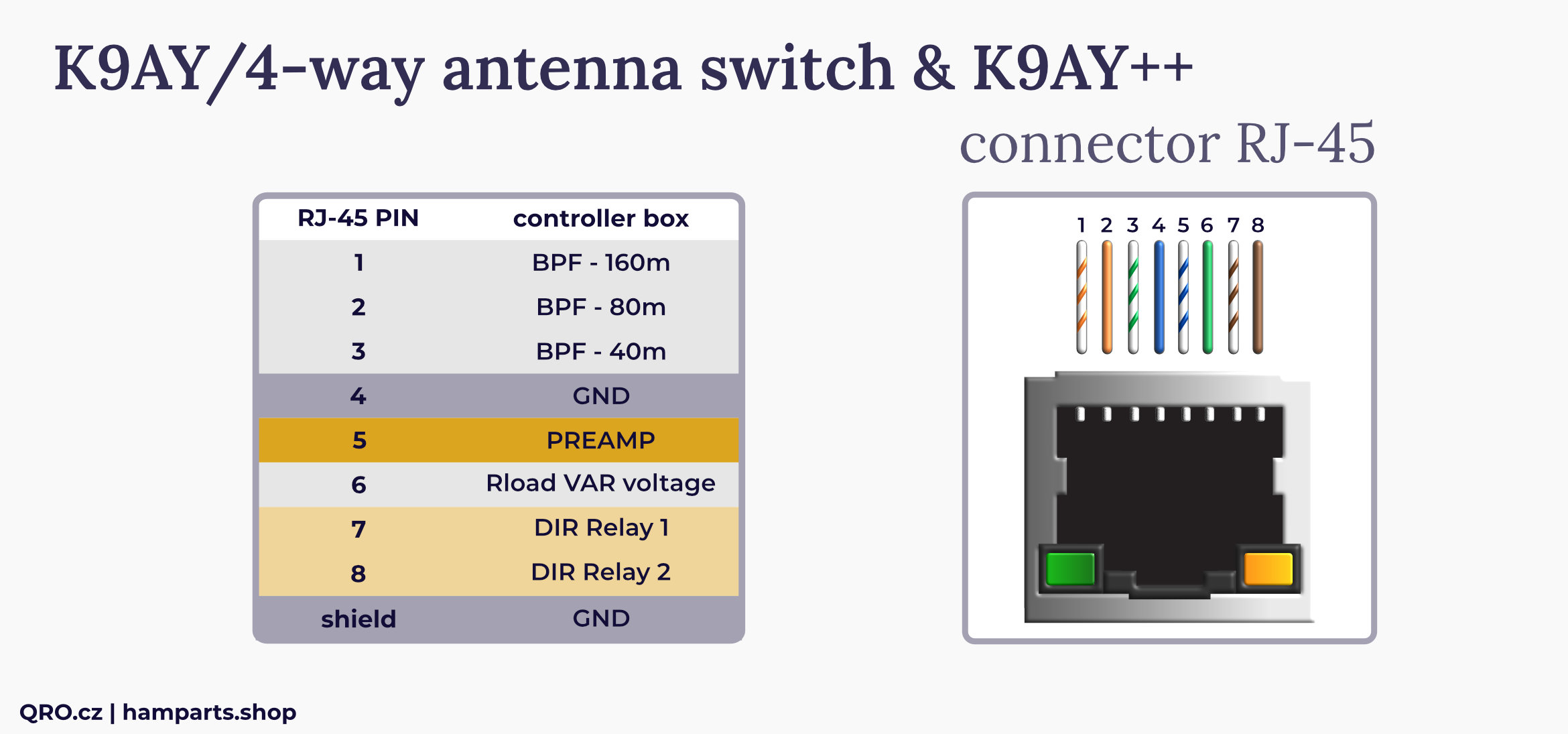
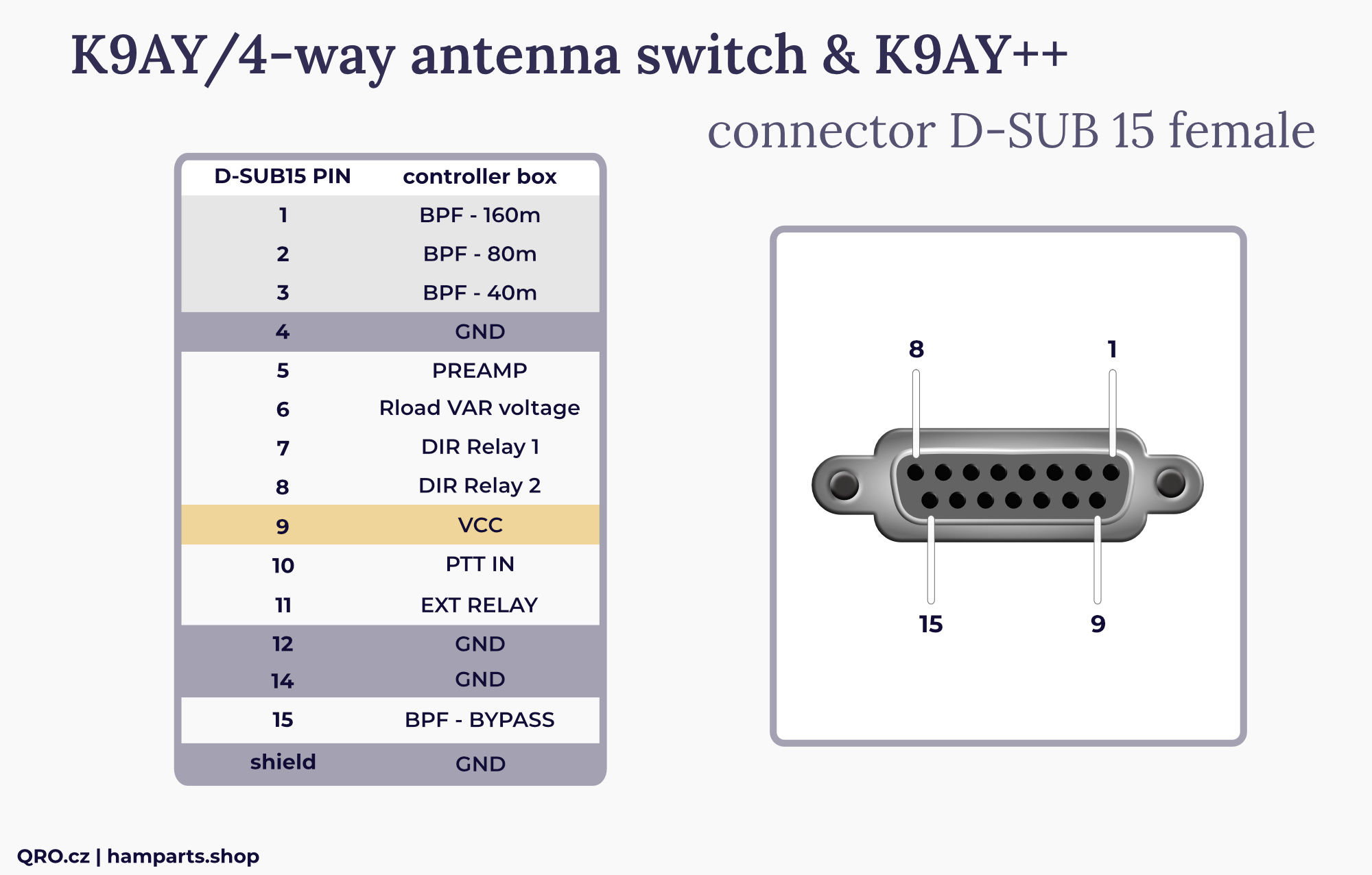
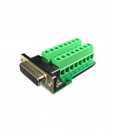
Connectors description
There are two ACC connectors:
- RJ45 and DB15F
- The first 8 wires are the same
- RJ45 is not LAN port! It is output to relays or feeder.
New version MK2 has got output FET drivers to offer lower voltage drop. There are included also extra TVS overvoltage protections.
*Vext at MK2 controllers. See more in the manual.
All signals there are DC voltage. Control pins have got voltage protection and basic RFI filter.
BPF pins - positive DC voltage switching Band Pass Filters
PREAMP - positive voltage switching ON preamplifier and bypass relays
Rload VAR voltage - DC voltage from front panel RLOAD switch. This voltage changes Rload (terminator) resistance in K9AY loop (or another your antenna)
DIR relays - DC voltage which controls directional relays in K9AY feeder box
PTT IN - the same as PTT IN RCA connector
EXT relay - DC voltage out. Follows rear small switch (K9AY/4-WAY) - you can use it to control external RF relay switching coax cable from controller to K9AY antenna and 4-way Bi-dir Beverage system. Please, have a look at example in this manual
BPF BYPASS - DC voltage out when BAND switch on from panel is to Bypass (No filter selected)
Vext (version mK2 2025+) - External voltage for output FET driver. You can apply higher voltage, when you use too long control cable between controller and K9AY++ feeder. See more in this manual.
REMOTE connector input
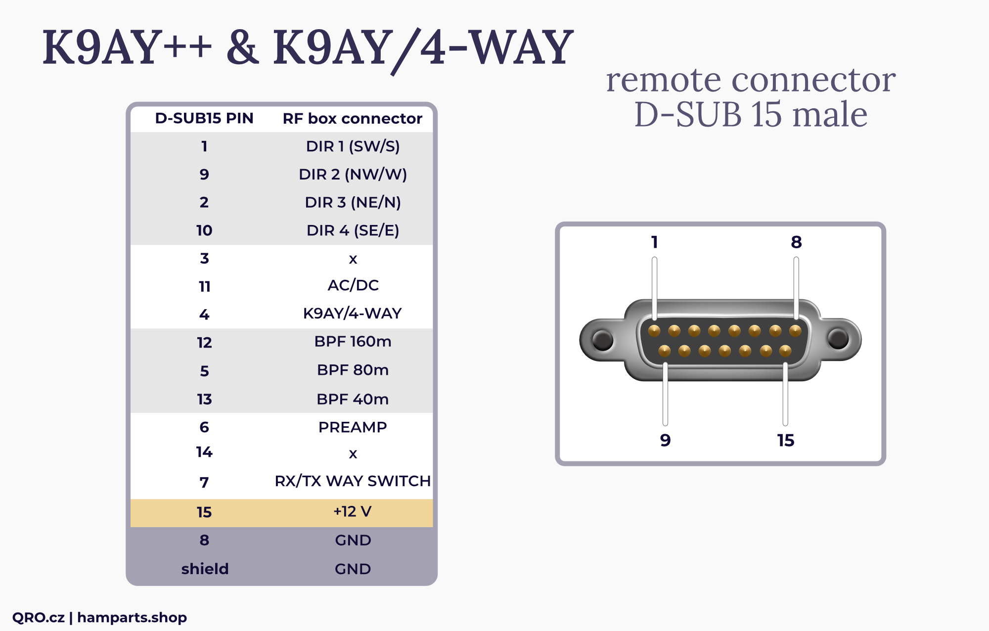
Controller with Remote option has got Remote Control DB-15M connector at rear panel of the enclosure.
How it works:
- When you apply +12V DC to any DIR pin, controller switches itself to remote control and front panel switches are disabled. Only all LED diodes work.
- Versions older than 2025: All input DC voltage from this connector go directly to rest boards. For example Preamp voltage at this connector directly supply preamplifier. Goes via the voltage protection and RFI filter.
- MK2 version has got output FET driver to eliminate voltage losses.
DIR - use one of this four pin to control direction
AC/DC - voltage from input Jack. Voltage from power supply - could be AC!
K9AY/4-WAY - switching matrix tables between K9AY and 4-way Beverage system. There is also output voltage for the 4-way position at ACC DB-15F connector. This is for optional RF relay. See picture in this manual.
BPF - voltage there switches ON BPF. If there is no voltage at any BPF pin, then Bypass is selected - wideband.
PREAMP - switching ON preamplifier. This voltage goes directly to Preamp
RX/TX WAY SWITCH - no voltage = TRX to TX/RX antenna port, +12V changes to RX from RX ANT port
+12V - this is voltage which you can use for switching all their features. Even if the controller is supplied by AC voltage. Have a look at the next picture.

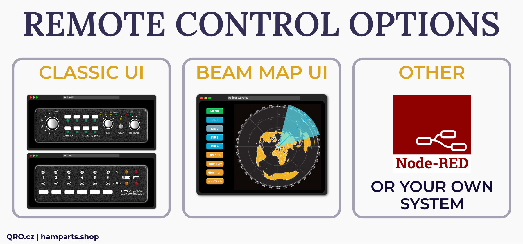
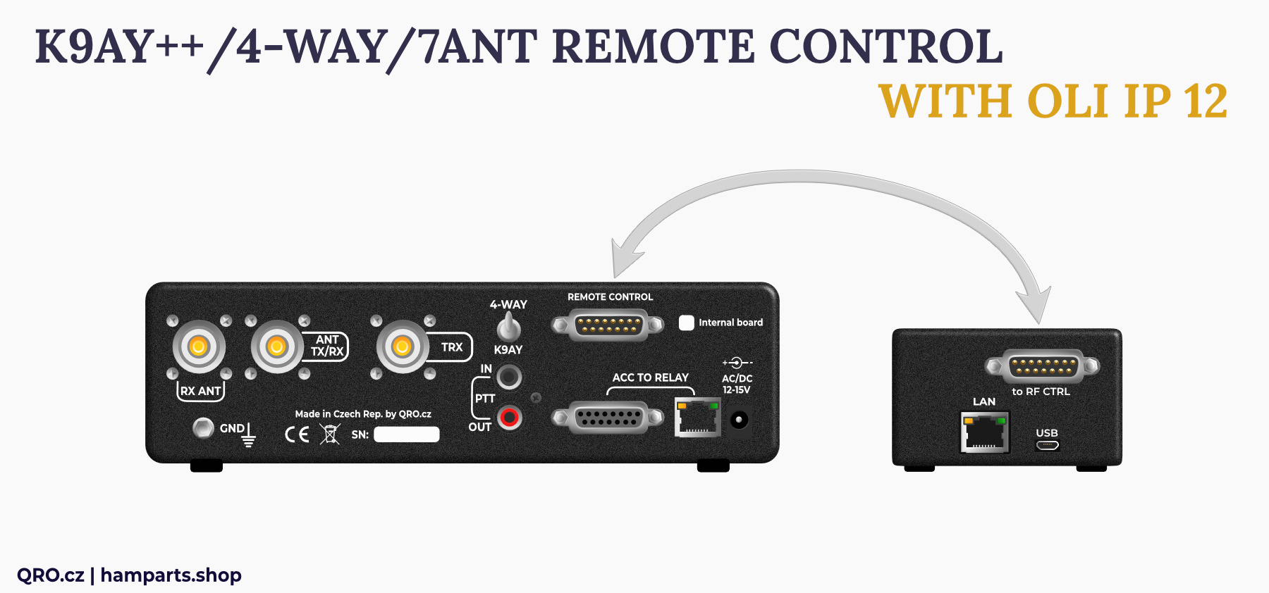
Remote Controllers
We offer a few web-based controllers. OLI IP 12, which is directly designed for K9AY++, 4-WAY and 7ANT RC controllers and REMOTIUS 64, bigger controller which could control more parts and offers more outputs. If you want to know more about REMOTE SYSTEM, please read our technical articles.
There is more ways for remote control:
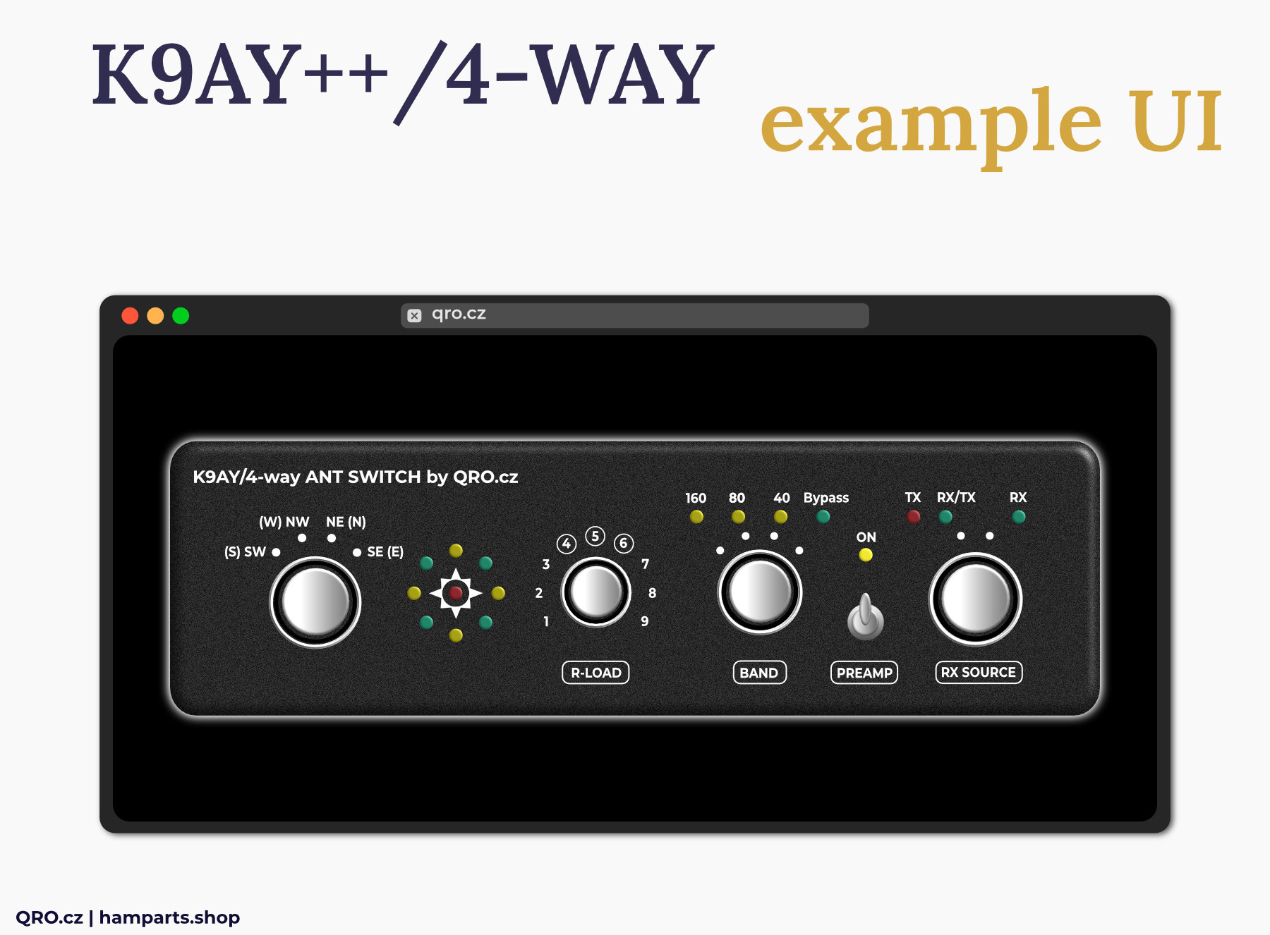
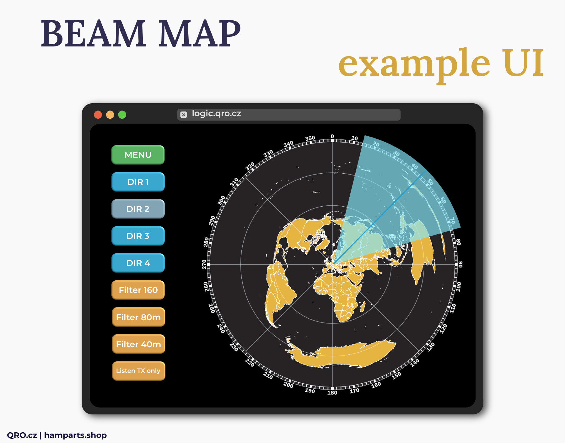
- Classic UI
- Beam Map
- Stream Deck, NodeRed or custom system
Application
This manual describes two controllers. All three main boards are the same. The only difference is in Band Pass Filters and Preamplifier. K9AY++ system has got these parts inside the Feeder box - there is no BPF and Preamp in the controller. Controller for 4-WAY Beverage system has got it as internal board inside.
You can use K9AY++ controller also for 4-way Beverage system but in this case the BPF and preamp work only with K9AY++. Beverage system cannot use it. In the case of K9AY/4-way controller you can use simply K9AY feeder and Bi-dir Beverages where there BPF and preamp work for both antennas. Please, have a look at the Block Diagrams and photos.
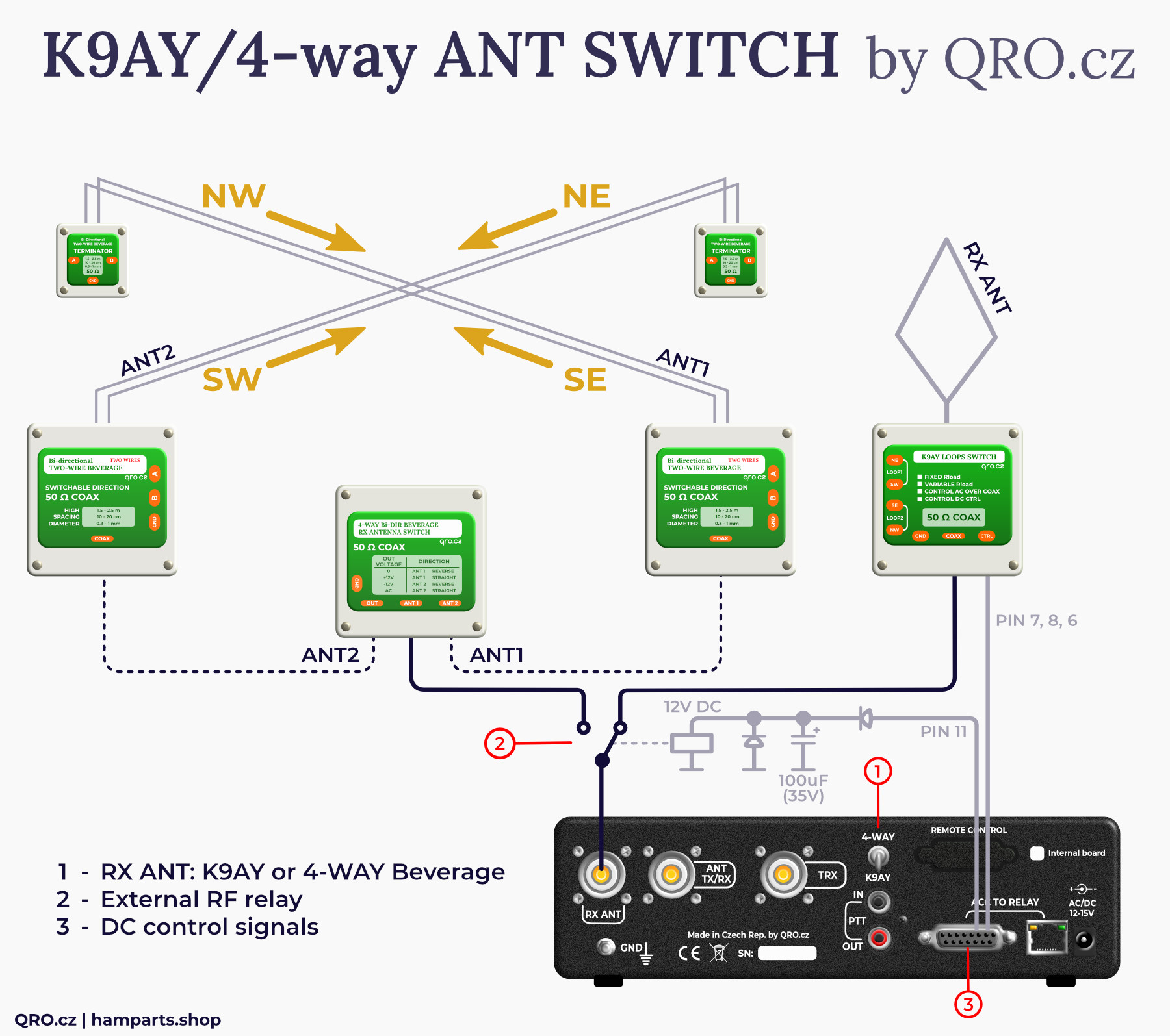
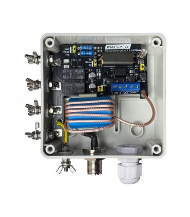
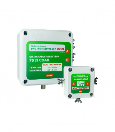
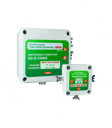
Example for K9AY/4-WAY controller with internal BPF and Preamp board
- You can use it for simply K9AY (also K9AY++ there with 2x BPF and 2x Preamp) and 4-WAY bi-directional Beverage system. You have to use 12V AC power supply. Controller then can use own matrix tables for K9AY and 4-WAY and sending +12V, -12V and AC over the coax - have a look at the jumpers settings
- You can use external RF relay to switch coax cables between K9AY and 4-WAY. This relay is controlled by the small switch at the rear panel of controller. This switch also selecting right switching matrix table.
- Have a look at the connector pin description
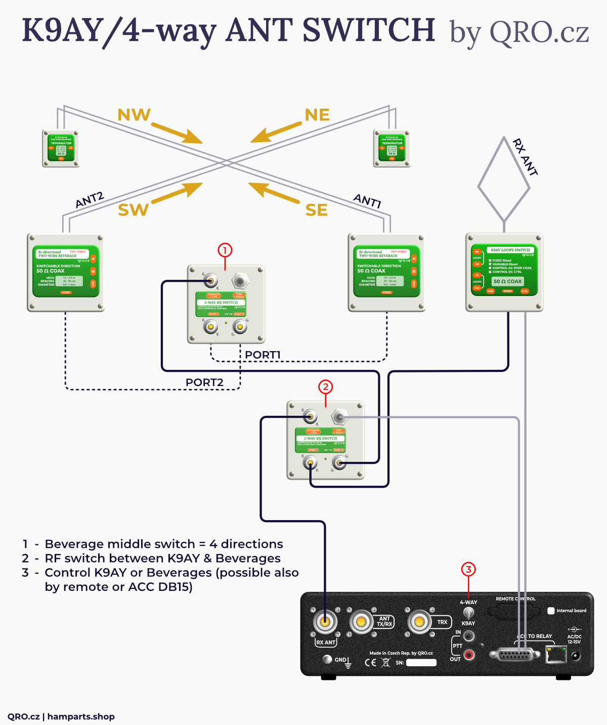
You can use 2-way switch there too
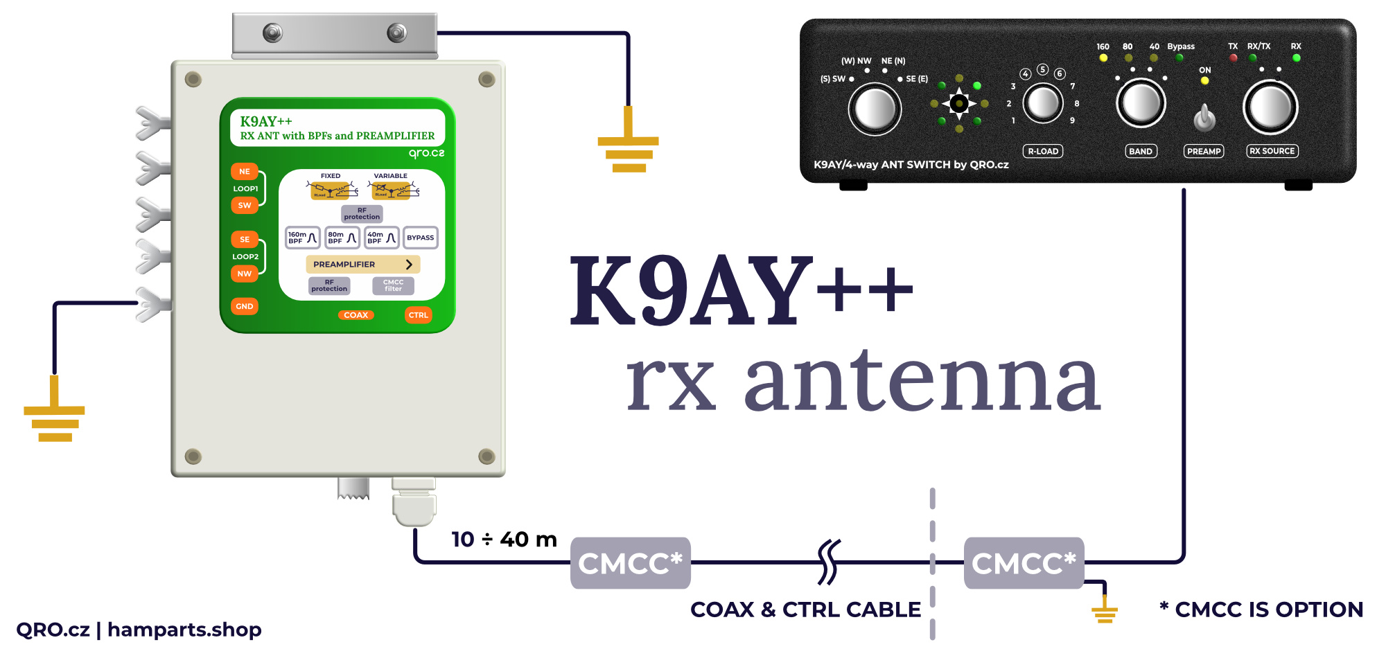
Example for K9AY++ antenna system
- There are two boxes: controller and RF feeder
- Connection between controller and feeder is by 8 wires
- You can use copper version of CAT-5 (6) LAN cable (FTP is recommended)
- This controller does not have BPF and Preamplifier inside - these parts are in the K9AY++ feeder box. Have a look at the block diagrams.
- There are optional CMCC at the picture. You can use it to be sure to avoid problems with the common-mode currents and noise.
PTT information
Study the controller wiring with your TRX - you may not need to connect the PTT signal at all. See here: manual.
The controller allows two ways of PTT detection:
- - Sniffer, whre the contoller only listens to the PTT signal. The advantage is that PTT is not interrupted from IN and OUT even when the controller is off.
- - FET output, where PTT IN is detected and PTT OUT is switched by the FET transistor. This option only works when the controller is on.
The default setting is FET and is also recommended.
You can set this setting by Jumper - PTT OUT
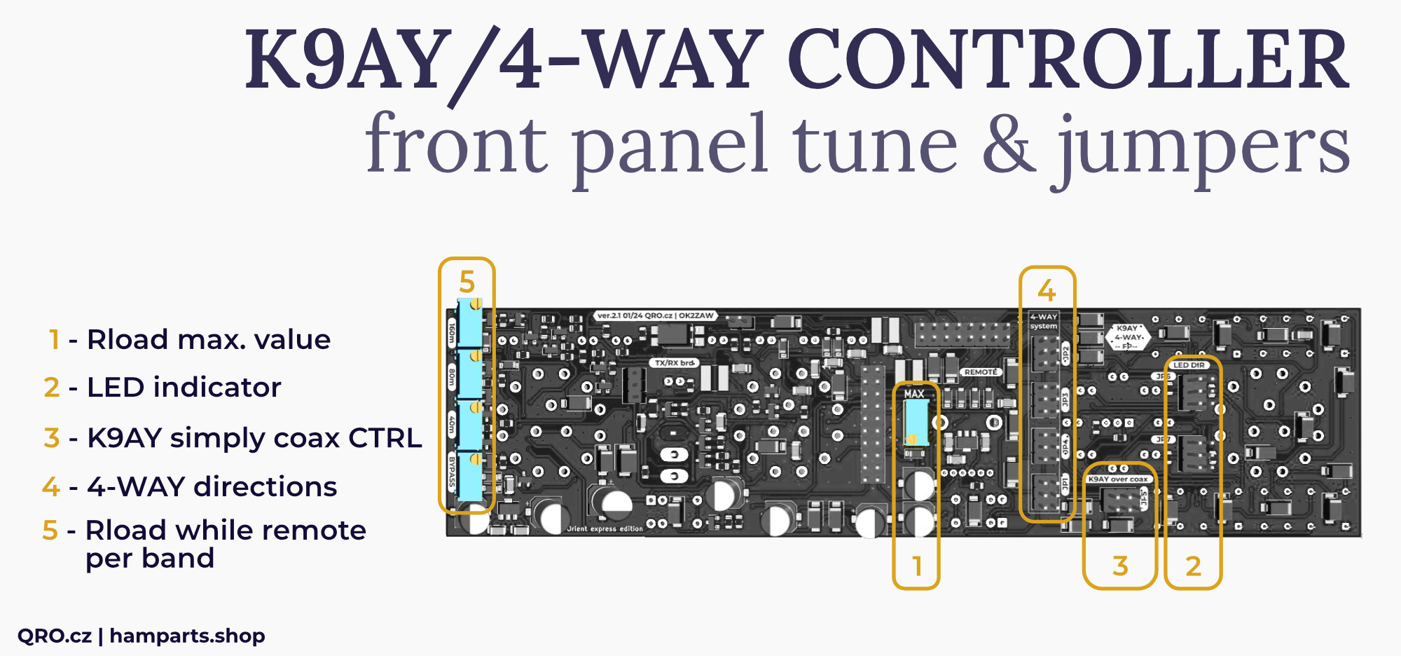
Jumpers settings
There are some jumpers and one trimmer which allow you to set a few things. Please, have a look at the right front panel version and notes for each jumper and trimmer.
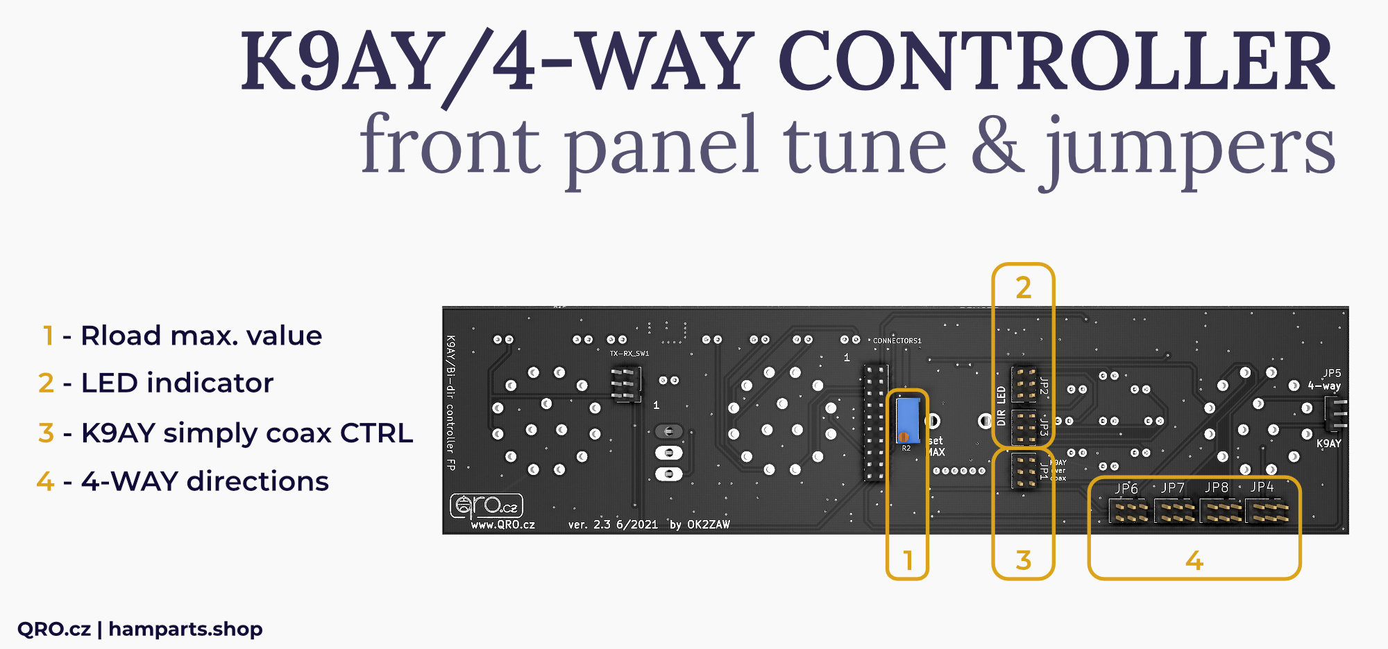
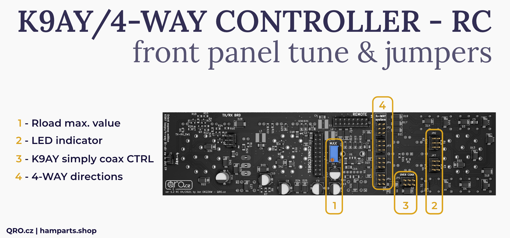
1. Rload max. value
- You can set maximal Rload (K9AY loop terminator) resistance
- This maximal value is at 9 point (switch R-LOAD at the front panel)
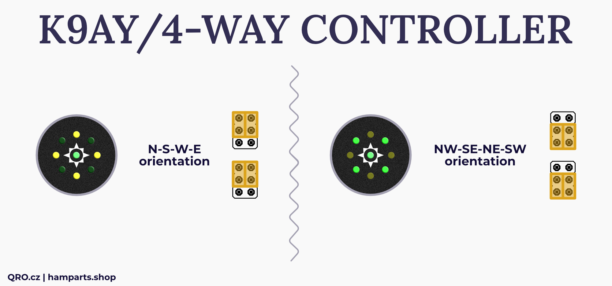
2. LED indicator
- You can set LED indicator orientation
- This depends on your antenna system location
- You can use N-S-W-E or NW-SE-NE-SW. Please, have a look at picture below
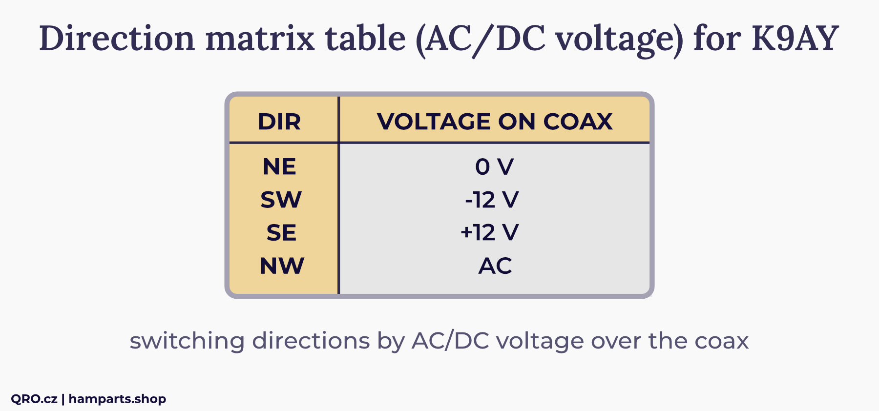
3. K9AY simply coax CTRL
- These jumpers are there for simply K9AY feeder which has got direction control by the voltages over the coax
- You have to use 12V AC power supply for controller
- Be careful - when you short this jumpers - there will be voltage on RX ANT connector
- Have a look at the matrix table for simply K9AY (one of the pictures below)
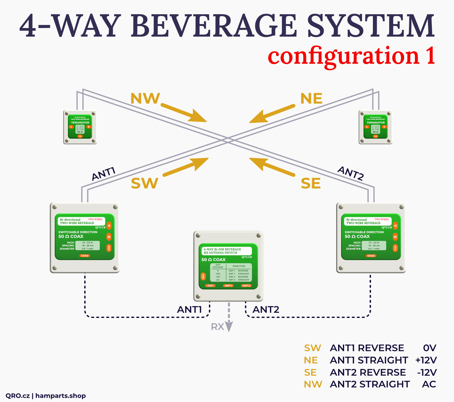
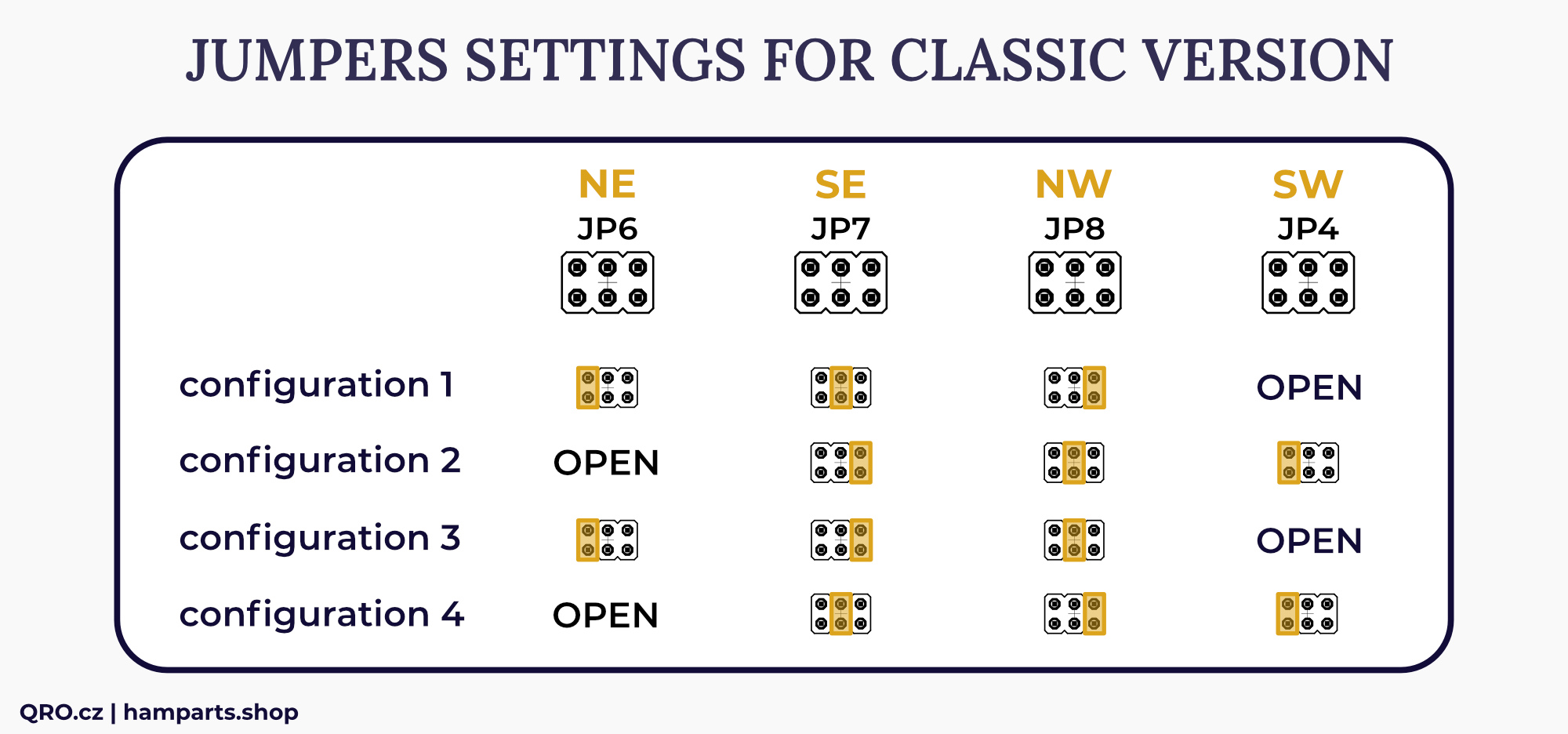
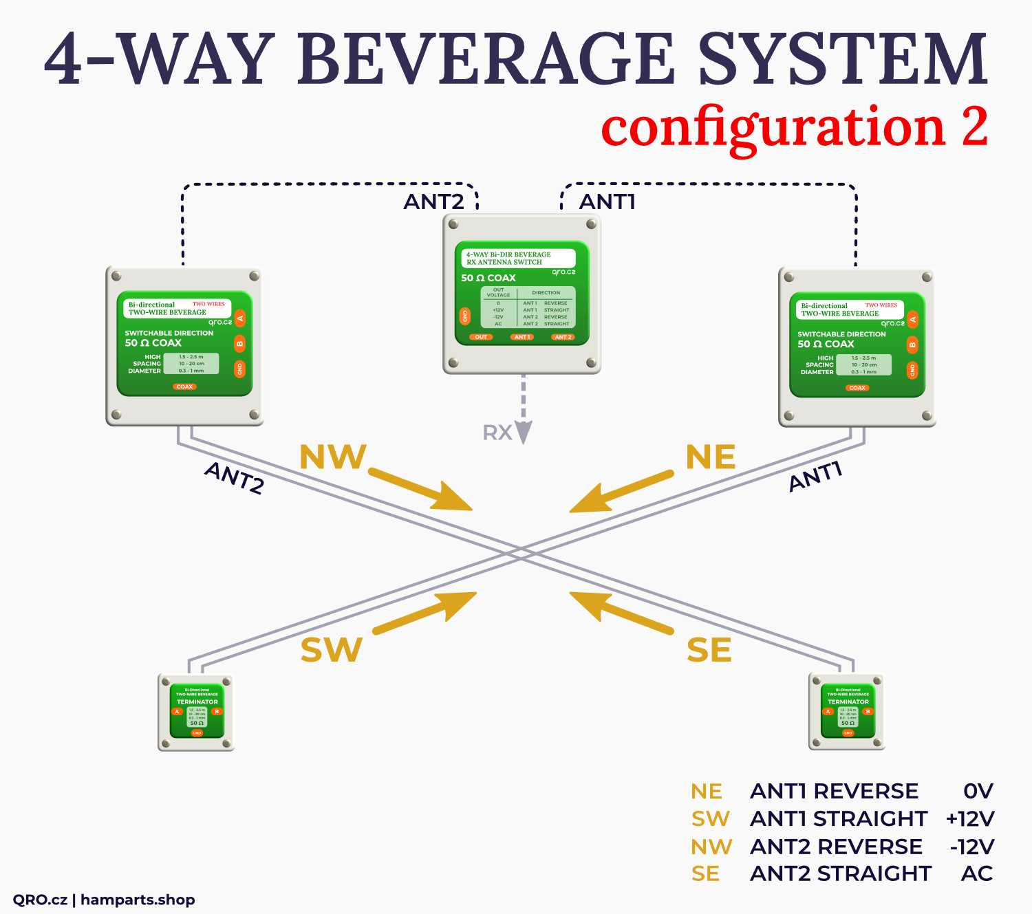
4. 4-WAY directions
- These jumpers set matrix table for 4-way Bi-directional Beverage system
- Please, have a look at four examples of your antenna locations and coax connections
- You can short jumpers which you need. There must be 12V AC power supply for the controller and there will be voltage at RX ANT connector
K9AY matrix table
This is matrix table for the simply K9AY feeder. Controller is needed by 12V AC power supply. There are diodes making necessary voltages for K9AY feeder.
You have to enable coax control by jumper - more in Jumper settings. You can use DC output at ACC to Relay connectors.
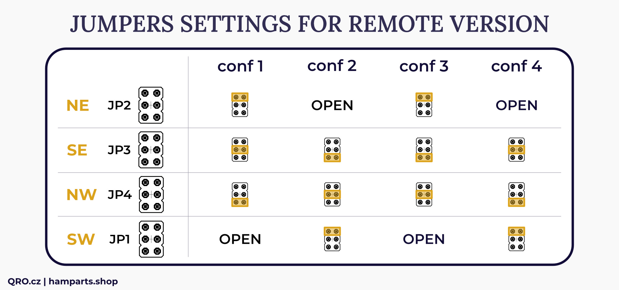
4-WAY antenna system matrix tables
There are two matrix tables for classic and remote (MK2) controller versions. Each table has 4 different configurations - each configuration is one kind of your antenna location.
You can find more in this article
⚠ older manual page for serial number < 2022 - more info in article
Settings for older Classic version of controller
Settings for remote and MK2 version
PTT settings
Jumper J4 PTT OUT at rear connector PCB.
Vext settings
This is only at MK2 version. You can use the same voltage as is connected to the DC jack or you can connect external voltage. Usually higher because there is too long control CAT-5 cable and there is too high voltage drop.
You can connect external power supply, like 15V DC when the CAT-5 cable is more than 100 V long. This is for experiments and checking the voltage in the feeder box.
You can set jumper J6 between CTRL and Vext.
External voltage could be connected to PIN 4 at DB-15 ACC to relay connector. See the connector description.
⚠ This is only available at MK2 controller with serial number 25xxxxx. You can check internal PCB version and also beep PIN 4 to ground. Ask if you are not sure. Do not use higher voltage than 20 VDC.
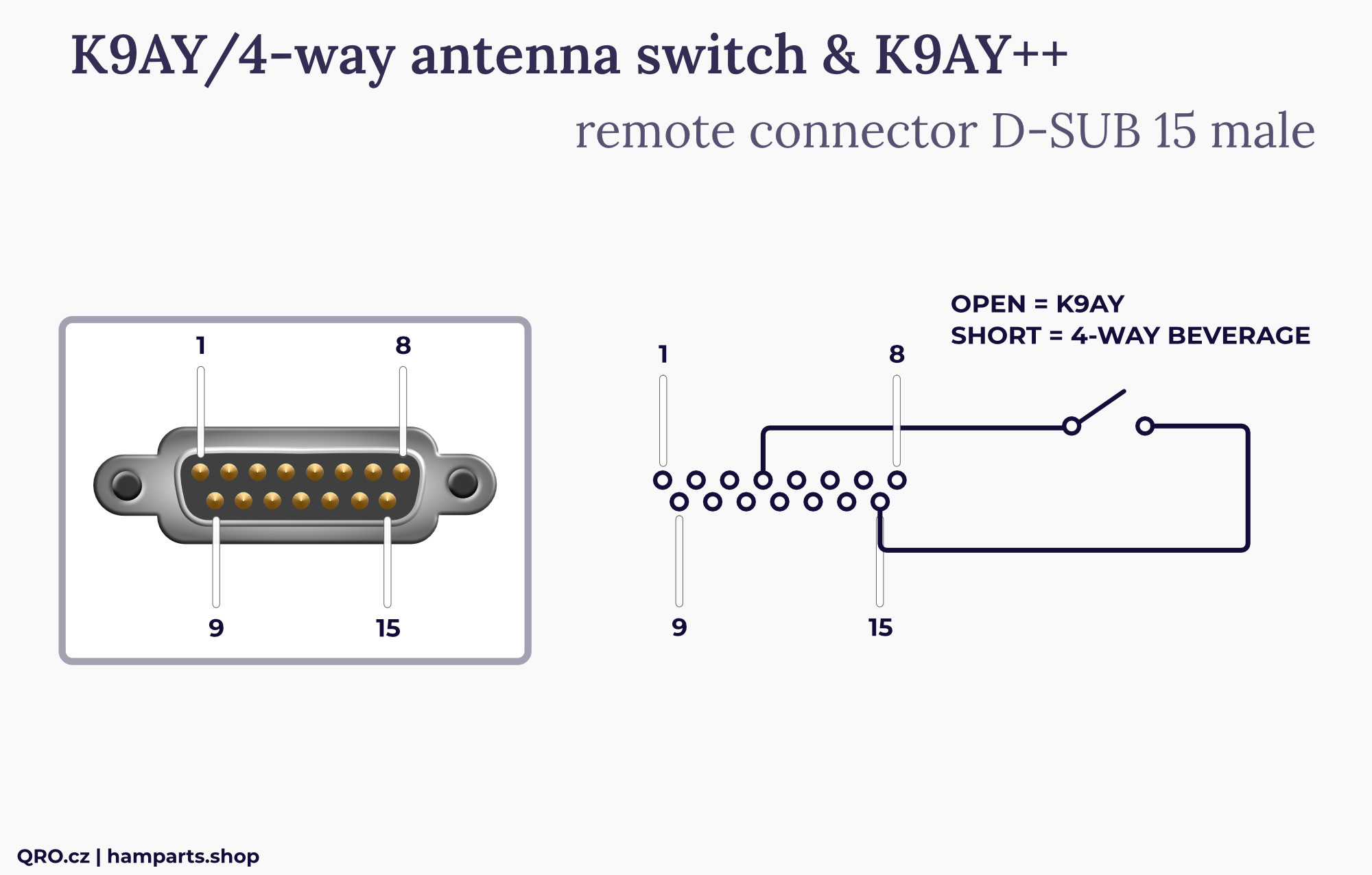
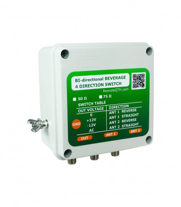
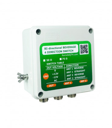
4-WAY/K9AY external switch
The controller allows to control both K9AY and 4-way Beverage antennas. The control is possible via coaxial cable and a picture with an example can be found in this manual.
Directional matrix switching for these antennas is implemented by a small switch on the rear panel. This switching can be inconvenient. If you have a controller with a REMOTE input, or the MK2 version, you can connect an external switch to the REMOTE connector to switch between Beverage and K9AY. Then you switch the direction with the front panel knob and just choose which antenna is involved.
Connect external switch between PIN 15 and PIN 4 at D-SUB REMOTE connector. Open is K9AY, short is 4-WAY Beverage system.
Variable Rload resistance
The controller offers the possibility to change the Rload resistor in the antenna, for example in K9AY. Our K9AY++ offers this option. If you would like to experiment with your own antenna, you can use for example Vactrols.
Use the potentiometer on the front panel to adjust the output voltage and, consequently, the resulting resistance. However, there are additional trimmers inside the controller that can be used to adjust the center value of the potentiometer. The front panel knob can be used for manual control, but there are four trimmers inside for remote control. Three are for the individual bands (160, 80 and 40 m), and a fourth is for bypassing. This allows you to set the Rload values for each band and the bypass setting for remote control. These are four fixed values; they cannot be changed remotely. They are set inside the controller with blue trimmers (see photo).
Internal BPF and Preamp board
This is internal BPF and Preamp board. This board is part of the K9AY/4-WAY controller.
- There is input SMA at the right side of the board. Signal goes to 100 kHz High Pass Filter (eliminate AC noise) then to Bypass or Band Pass Filters (160m, 80m and 40m)
- Band pass Filters include also notch filters - better attenuation on next bands
- You can switch On preamplifier. Two blue trimmers are part of the preamp - one allows to set transistor BIAS current and second one works as variable attenuator. You can set total gain of the preamplifier from 0 to 18 dB
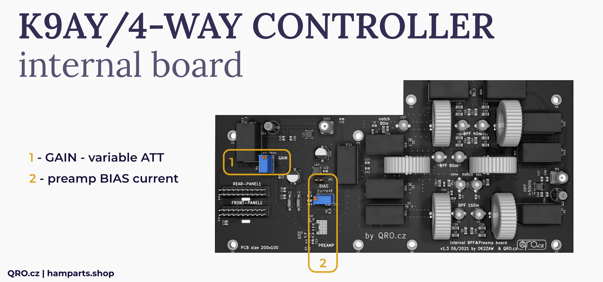
1. Gain - variable ATT
- Blue trimmer which works as variable attenuator
- You can set maximal gain of the preamplifier. Attenuation works also as wide-band load for preamp
- Preamplifier gain is pre-set to about 10 dB (from maximal of 18 dB)
2. Preamp BIAS current
- You can change and measure transistor bias current
- Connect power supply to controller
- Remove Jumper JP1 and connect mA-meter there (scale 200 mA)
- Turn the blue trimmer (current) and measure the current
- Bias current can be from 10 mA to about 70 mA
- Recommended bias current is 30-35 mA
- Please, do not use higher current. Transistor is 1 W, when you use 13.8 V and 70 mA it is almost 0.97 W!
- If you like to have low Noise Figure, set current under 25 mA - NF will be around 1. Higher current mean NF under 2.
continue to manual for K9AY++ feeder


