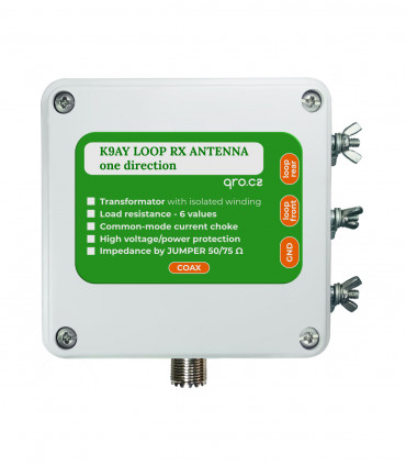
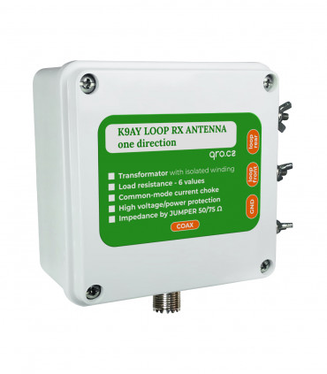
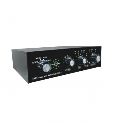
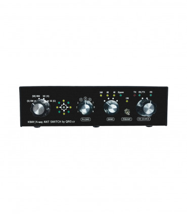
K9AY simply manual
This is technical manual page for K9AY simply feeder box. You can connect two loop antennas and switch four directions by the internal relays. Loop termination resistance could be fixed or variable. In the case of the variable Rload you are able to change resistance from 200 to 1200 Ohm. Direction relays could be controlled by external wires and DC voltage or by the coax cable with AC/DC. There are also front-end protections and you may not be worry about high power from TX antennas. This antenna needs good ground.
Jump to
Applications
Parameters
Schematic
PCB
Jumpers
Control
Article
FAQ
Product details
Applications
- Lower noise RX antenna
- RX antenna designed for FOUR directions
- Small design
- ideal for portable operation
- Noise source antenna for QRM eliminator
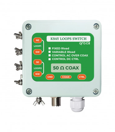
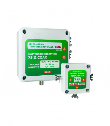
version with PL SO-239 connectors

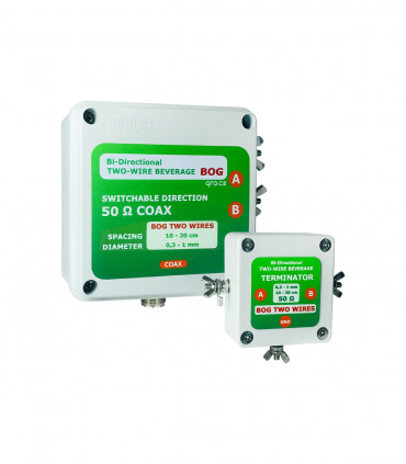
version with F connectors
Parameters
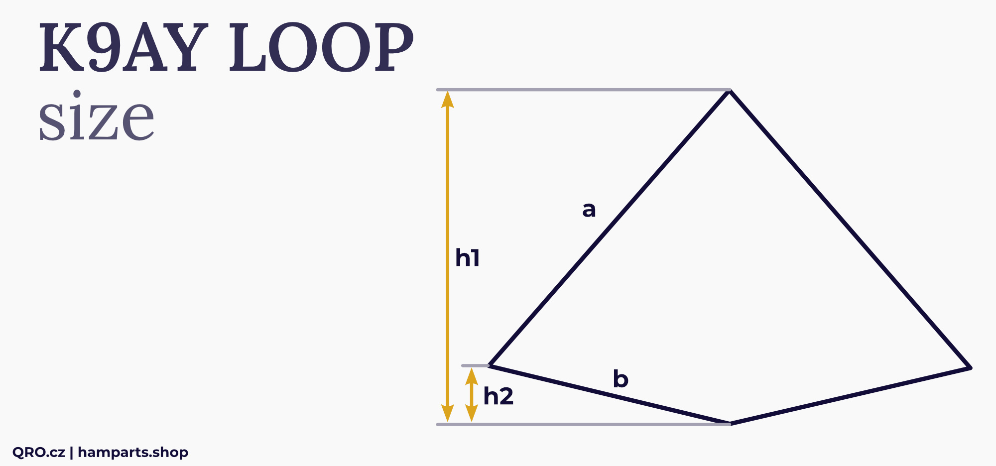
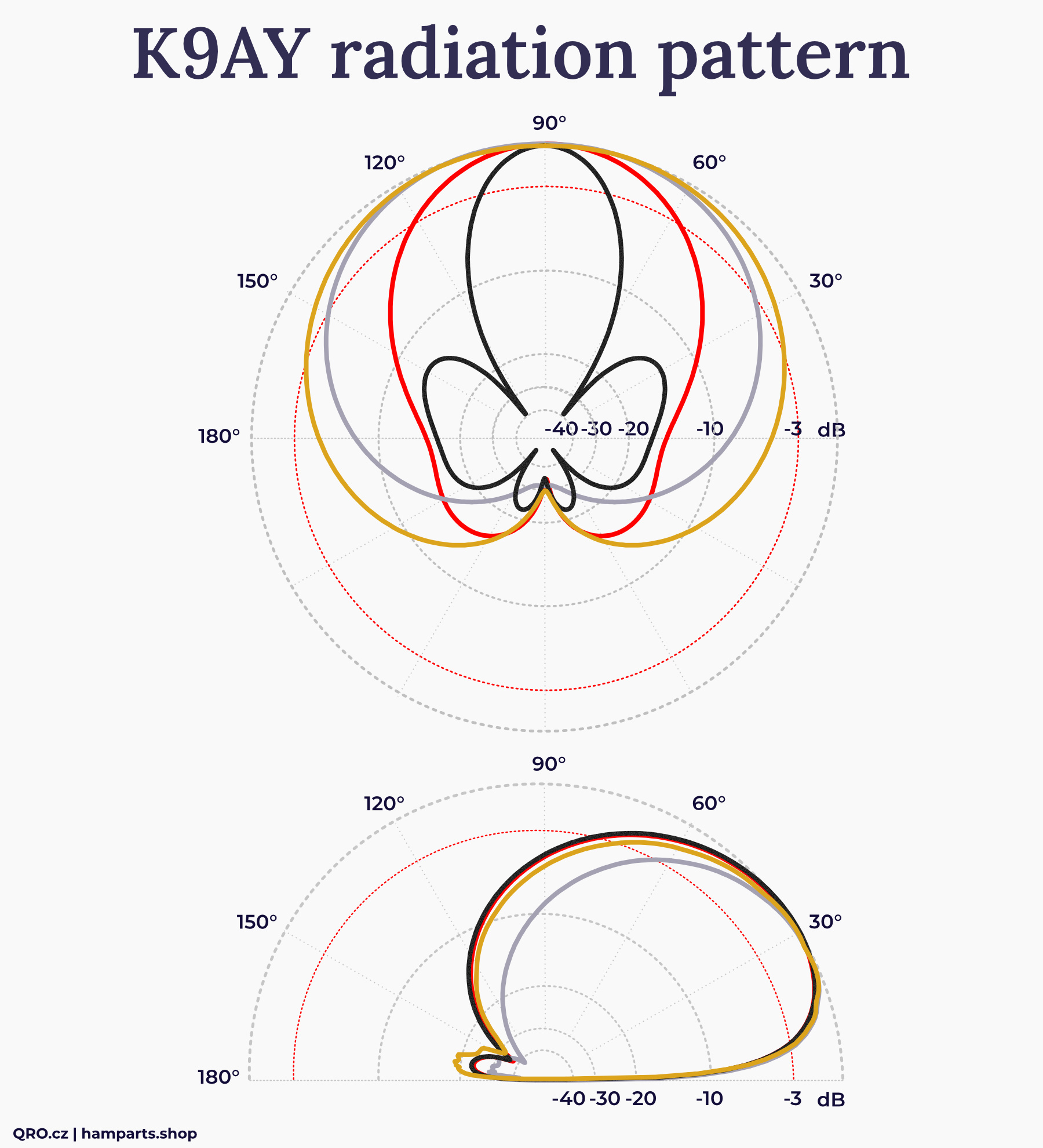
- RX antenna - Gain depends on loop size
- Four directions about 110 degrees
- F/B depends on loop size and construction
- Find more design hints (phased array)
- Feed line impedance 50 or 75 Ohm
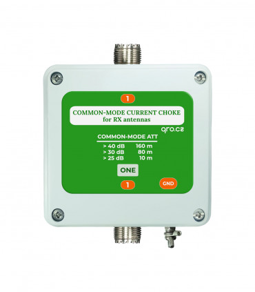
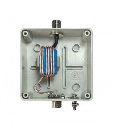
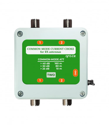
- Common-mode choke isolation more than 30 dB
- Current protection > 100 mA and Voltage protection > 65 V
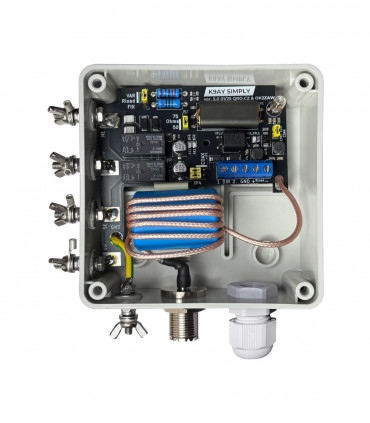
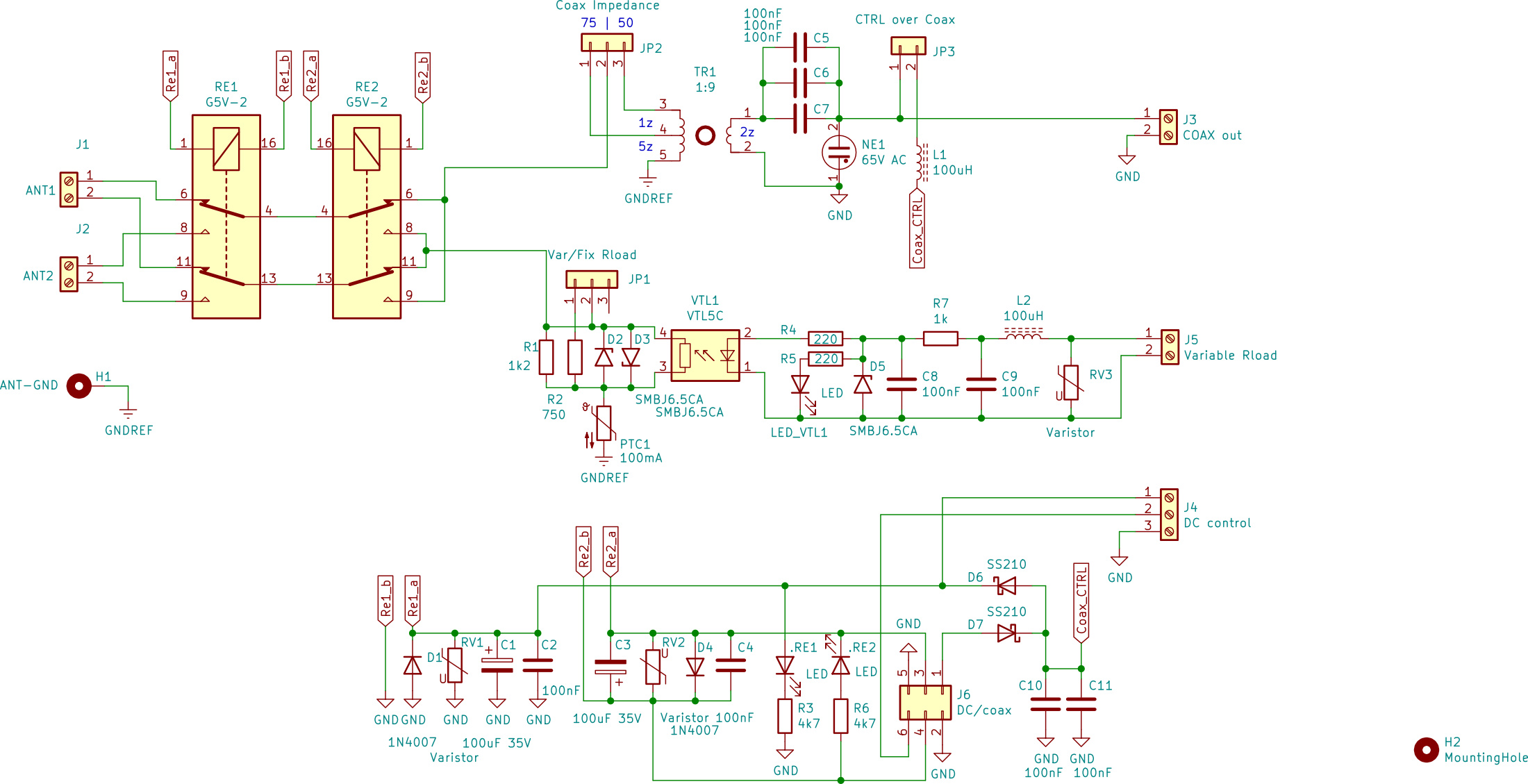
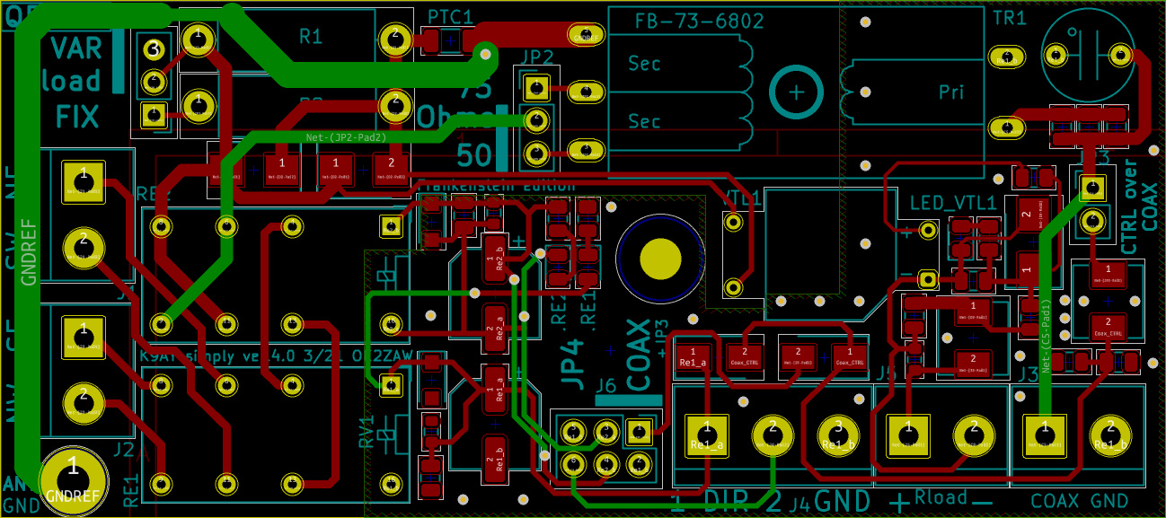
Schematic
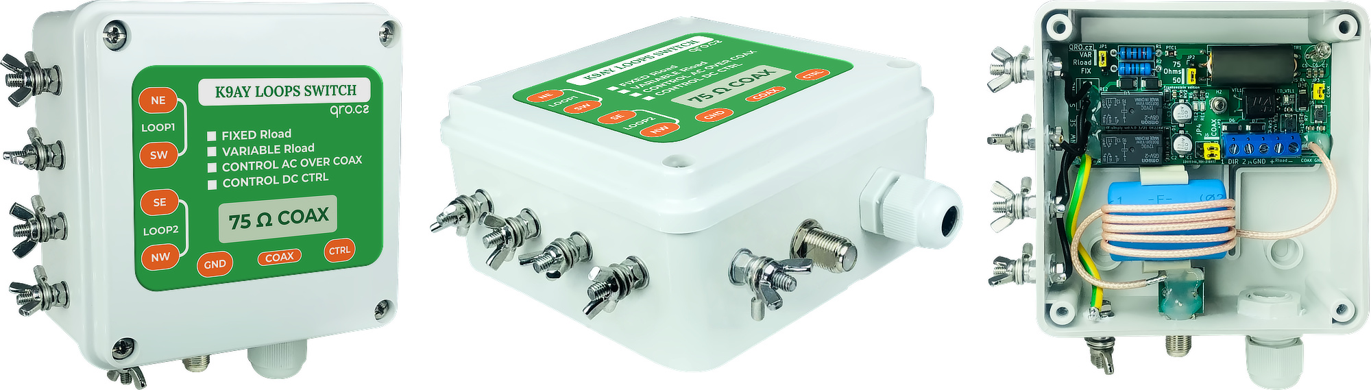
PCB
Jumpers
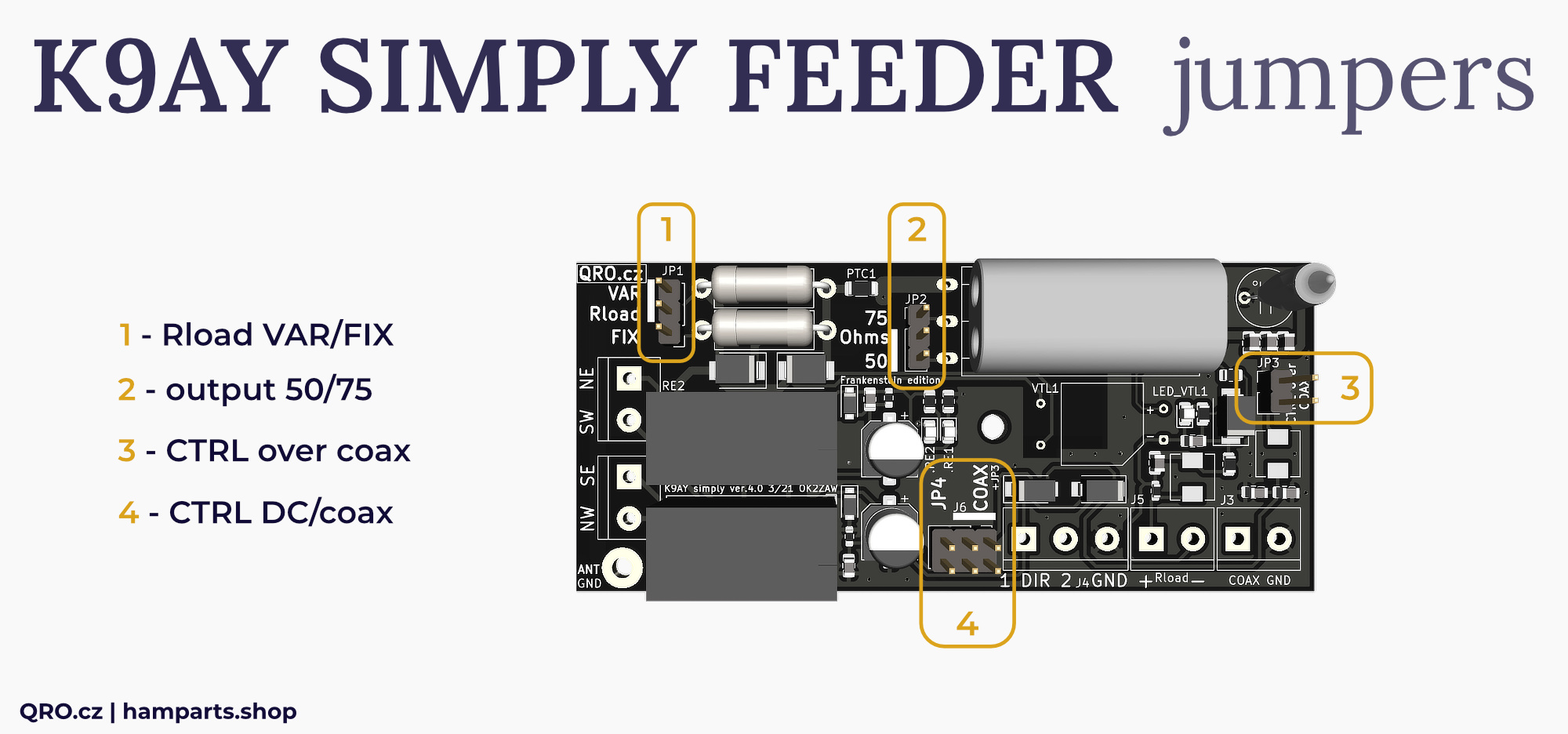
1. JP1 Rload VAR/FIX
- You can select Fixed load resistance to about 460 Ohm / 4 W
- If you select Variable one, you have to connect external wires and apply DC voltage in range about 1.5 to 6 V
2. JP2 Coax output impedance
- There you can select between 50 or 75 Ohm output coax
3. JP3 CTRL over COAX
- Short this jumper when you control direction of this antenna over the coax with AC/DC voltage
- Jumper JP4 must be switched to COAX position
4. JP4 CTRL DC/coax
- Select direction switching between External DC voltage at J4 connector or AC/DC voltage over the COAX (+ JP3)
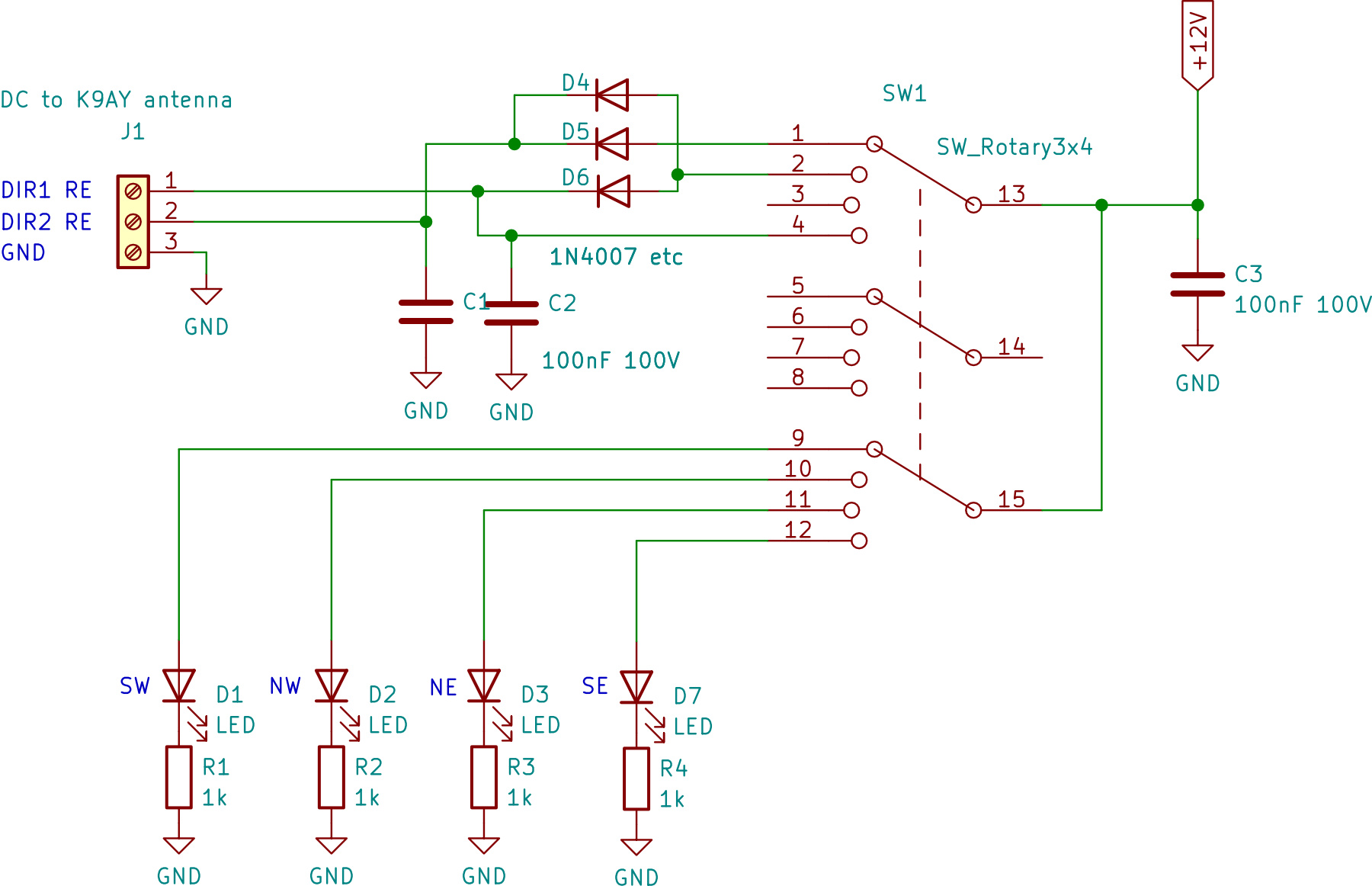
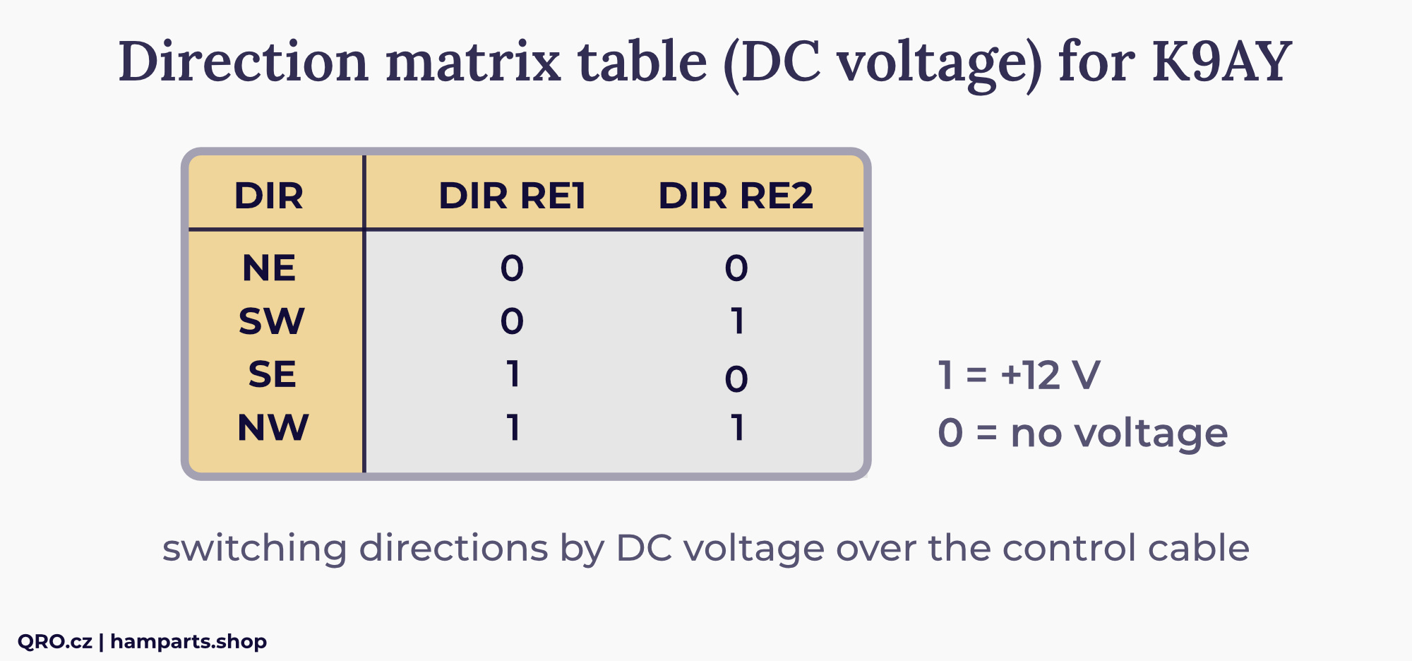
Control
There is example of the controller which is switching directions by the DC voltage. You need 3 external wires (DIR1 RE, DIR2 RE and GND)
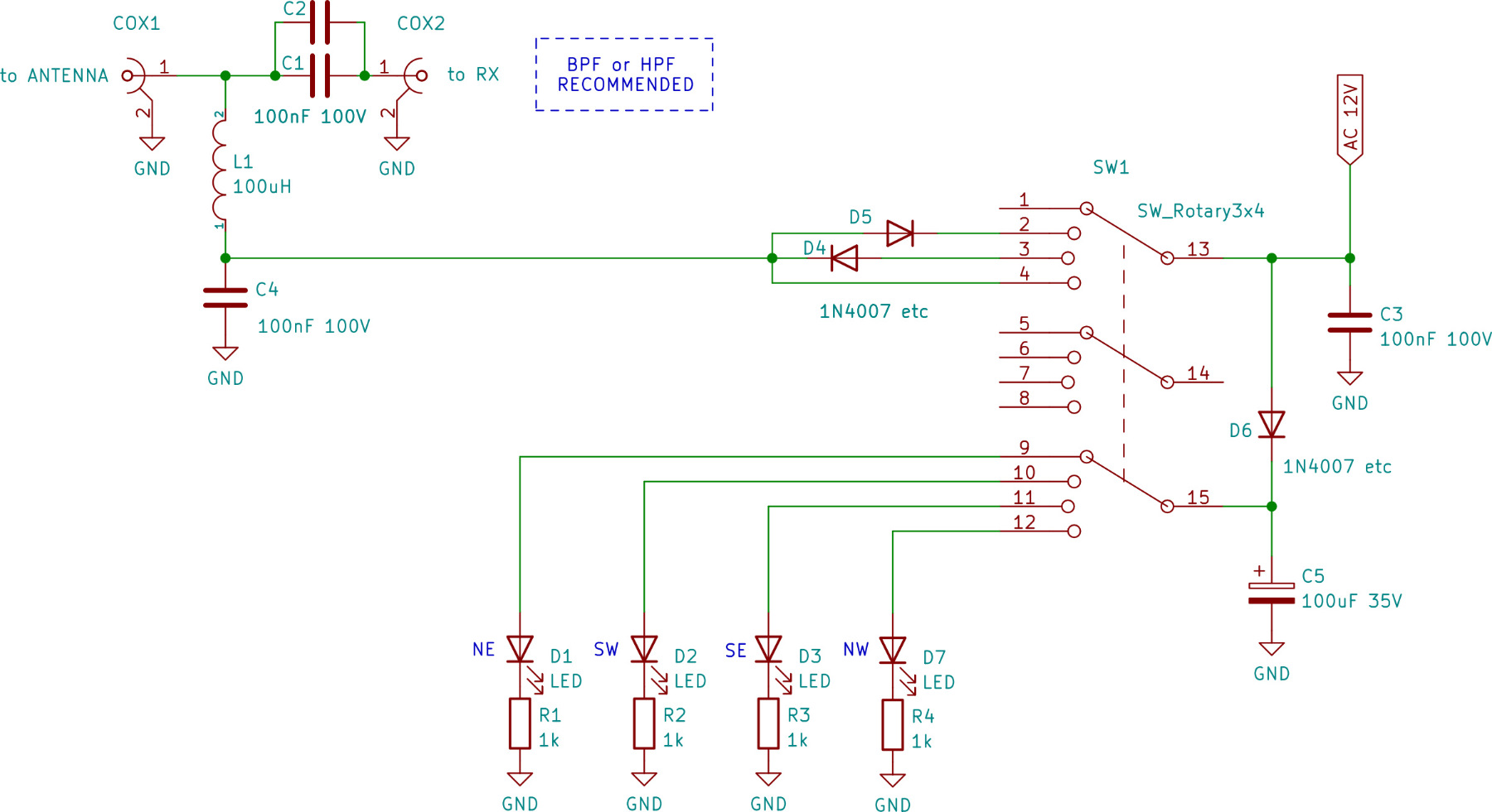
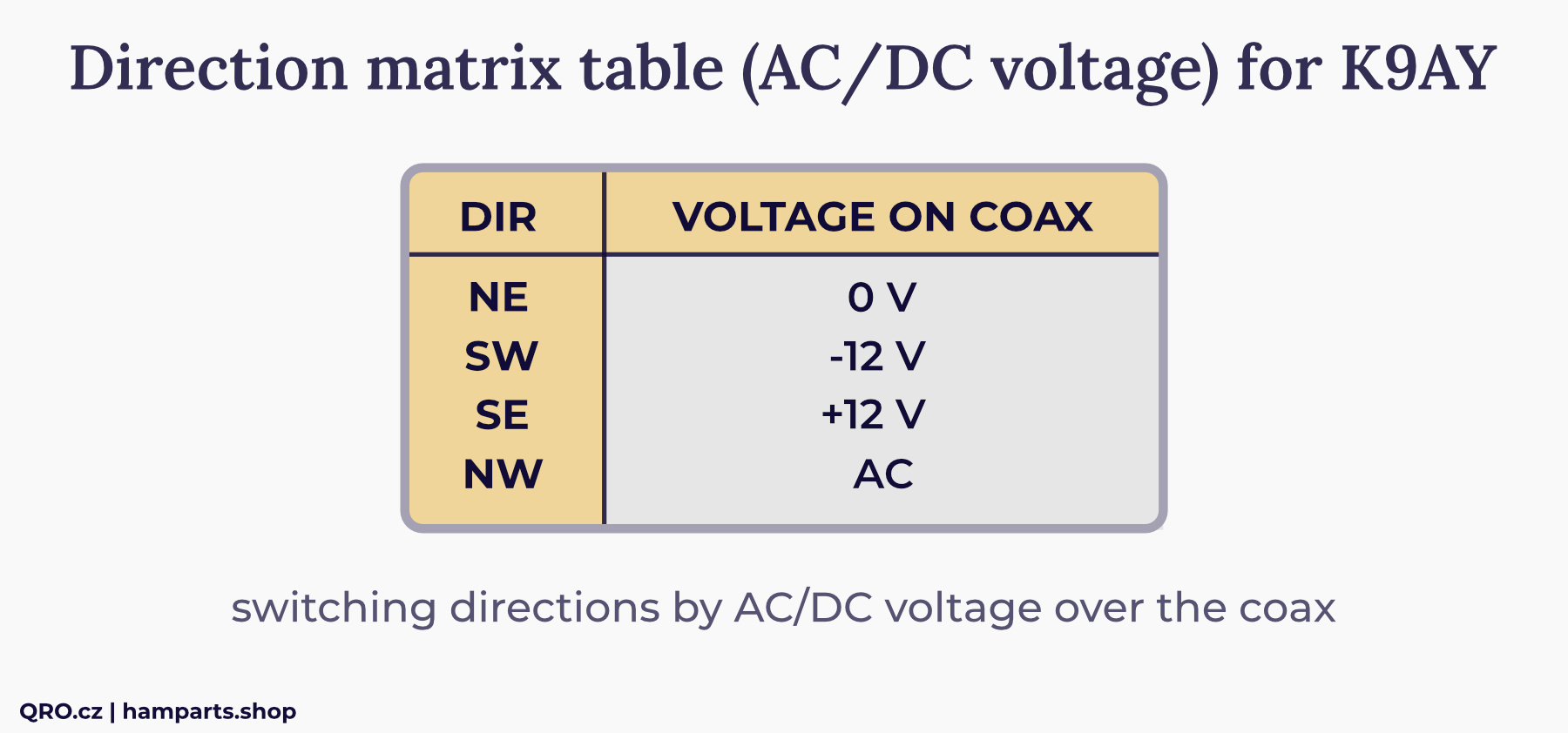
There is example of the controller which is switching directions by the AC/DC voltage over the coax cable. You need good Bias Tee to apply this voltage to coax and isolate it from RF. If you use Wide Band SDR, please use HPF or BPF to eliminate AC noise - you can damage your RX
Article
ℹ Read article about K9AY design and phasing array.