×

The beverage is a long wire antenna installed very close to the ground. The antenna should be longer than 1 wavelength and installed at a height of less than 0.05 wavelength above ground.

Beverage antennas provide one of the least expensive and most reliable ways to improve DX capabilities on the low frequencies. With careful attention to design and construction, a single beverage antenna can be made to cover two directions with excellent performance over a very wide frequency range. These are two beverage antennas receiving in opposing directions to share the same space. The transformer at the end of the beverage is designed to match impedance of the antenna.

A two-wire bi-directional beverage requires the antenna element to operate a balanced transmission line, as well as a conventional long wire antenna. The parallel wire line used to construct the antenna must be excited under near-perfect balanced transmission line conditions. This is why each of the parallel transmission line wires must be parallel to the ground. A line should not be constructed in a vertical fashion, using single support poles with one wire under the other. The closer the wire spacing of the line, the lower the impedance of the line, and the less critical installation-related unbalances become. The higher you install the line above ground, the less unbalance any unequal coupling to earth creates. (source: W8JI, ON4UN).

  Read article by Greg Smith, ZL3IX and article CLASSIC vs BOG beverage antenna.

Bi-Directional beverage

ONE COAX OUTPUT

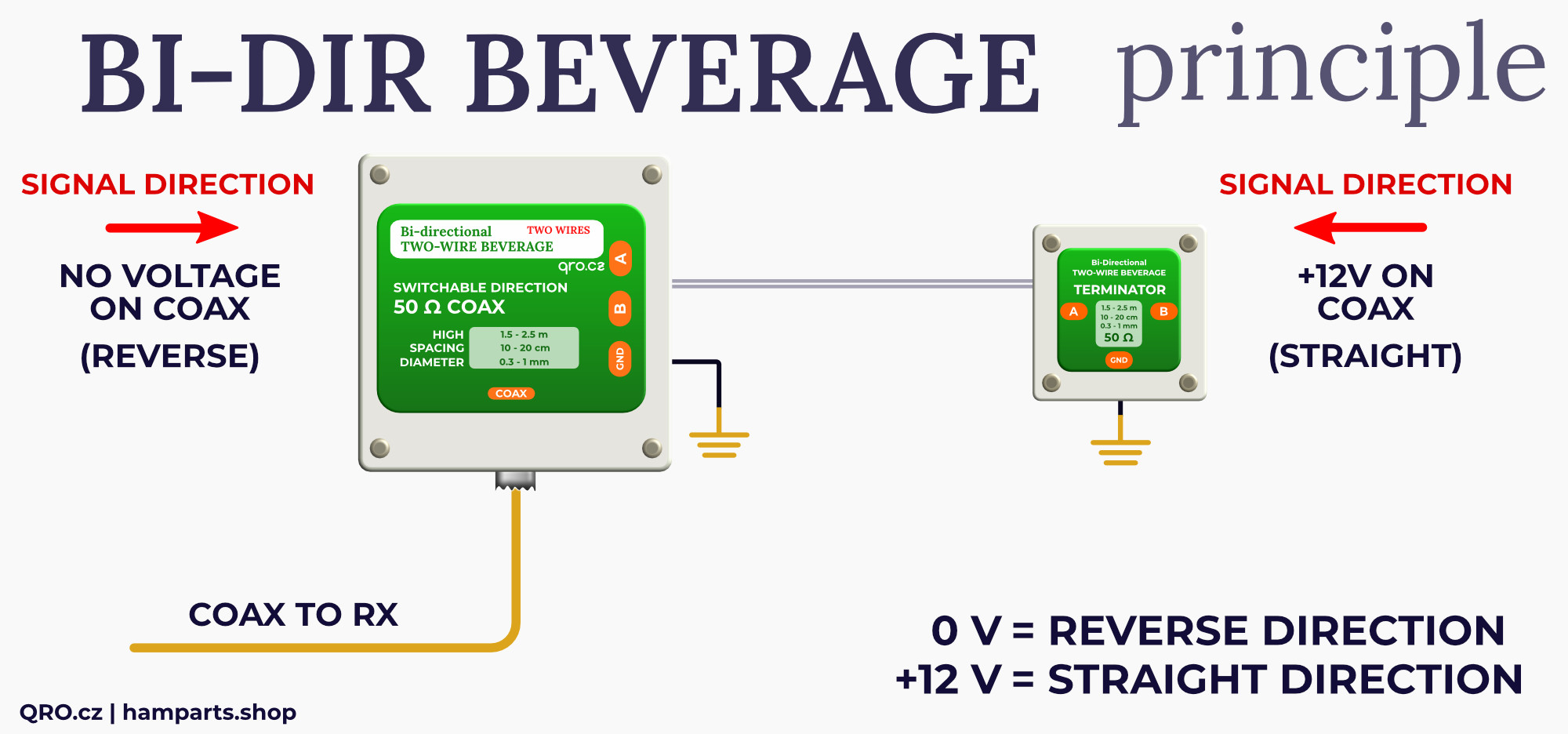
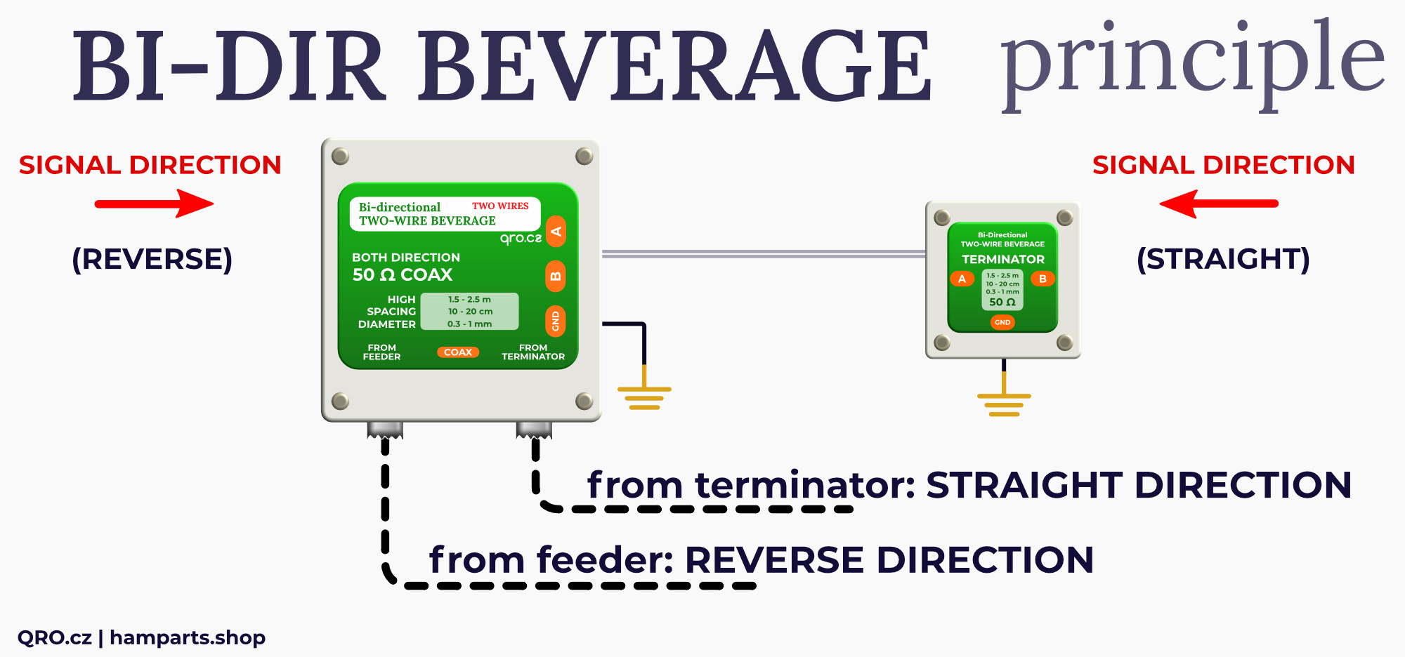
Principle of Bi-Directional beverage antenna 1 coax output

This one coax output version has got internal relay for direction switching. Control of the relay is over the coax. Without voltage the antenna has REVERSE direction (compare to single wire construction). With voltage on coax you switch to STRAIGHT direction (the same as on single wire beverage).

bi-directional beverage antenna principle 1 coax by qro.cz hampart.shop

Bi-Directional beverage

TWO COAX OUTPUTS

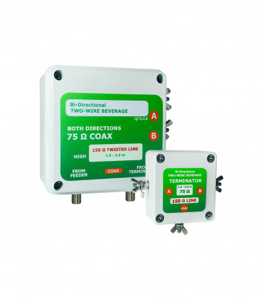
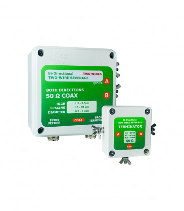
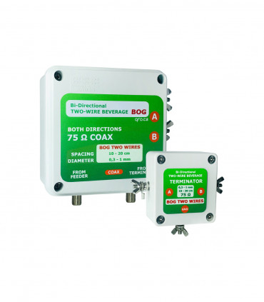
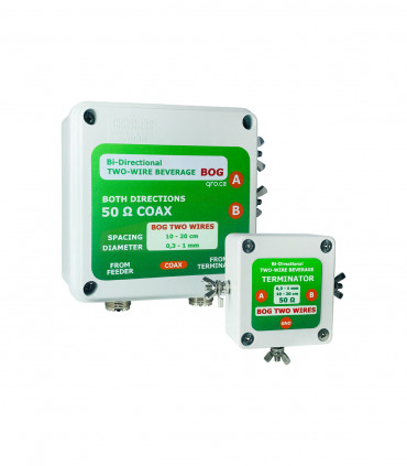
Principle of Bi-Directional beverage antenna 2 coax outputs

This version is designed for antenna direction sharing into the more RX. Together with our gears you can run SO2R or MM and share antenna outputs to more TRX. There are two output connectors with both directions from antenna at the same time.

bi-directional beverage antenna principle 2 coax by qro.cz hampart.shop

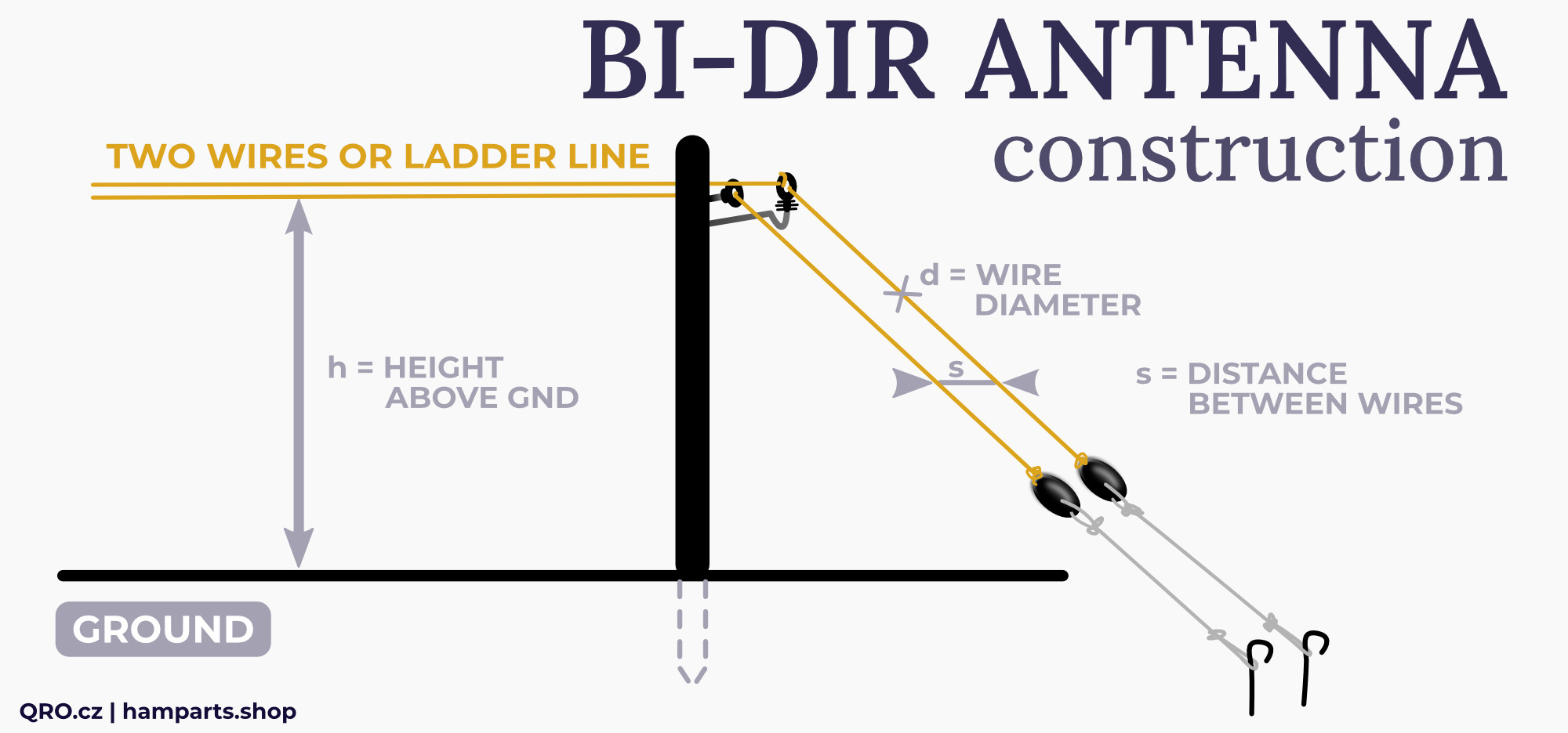
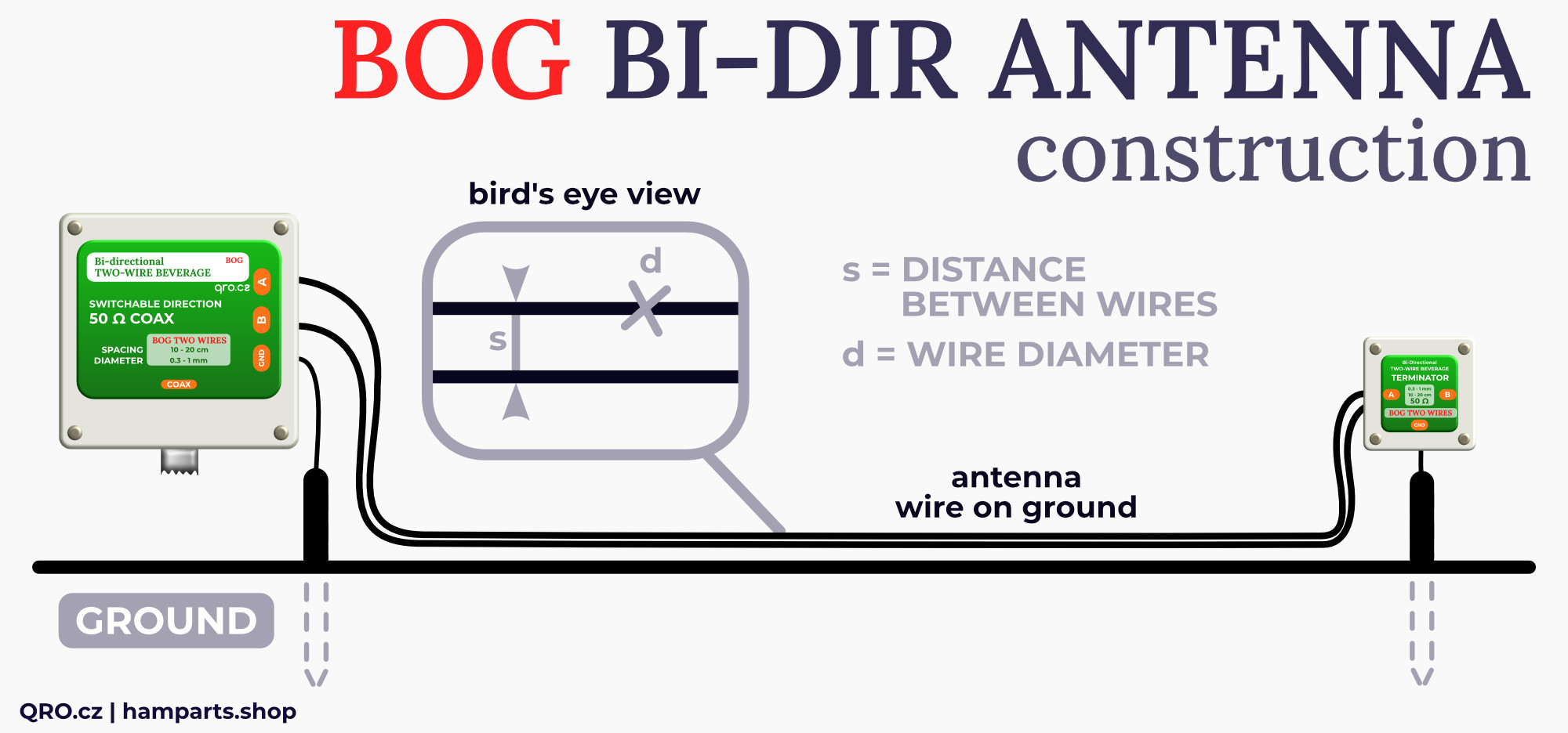
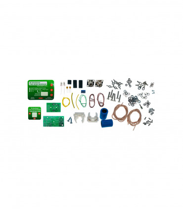
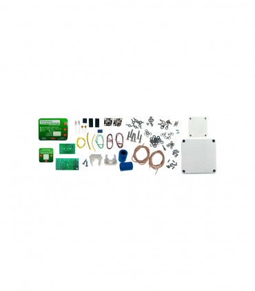
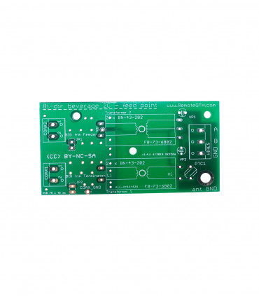
Construction of Bi-Directional beverage antenna

Beverage antennas should be installed more than a wavelength from other large metallic structures, such as vertical antennas, towers, power lines, electric fence wires etc. Antenna units can be mounted on trees, wooden pole or fiberglass rods - DO NOT use metal pipes and never mount this unit with the connectors facing up.

The parallel wire line used to construct the antenna must be perfect balanced transmission line conditions. The wires must be parallel to the ground. A line should not be constructed in a vertical fashion, using single support poles with one wire under the other. The closer the wire spacing of the line, the lower the impedance of the line, and the less critical installation-related unbalances become. When the antenna is ladder-line (300 or 450 Ohm) - twist the ladder line multiple times along its length.

bi-directional beverage antenna construction by qro.cz hampart.shop

bi-directional beverage antenna construction by qro.cz hampart.shop

Read Frequently Asked Questions

    • GND screw on feeder box is insulated from Coax shield. This isolation prevents introducing unwanted signals and noise into the antenna system. Grounds are insulated by Common-Mode filter.

  • Connect the ground terminal screws only to earth ground using at least one (copper/army GND rods with screw) ground rod. Use as large diameter ground rod as possible.

  • A good ground system improves performance (lower noise) and enhances lightning survivability.
  • The parallel wire line used to construct the antenna must be perfect balanced transmission line conditions.

  • The wires must be parallel to the ground. A line should not be constructed in a vertical fashion, using single support poles with one wire under the other. The closer the wire spacing of the line, the lower the impedance of the line, and the less critical installation-related unbalances become.

  • When the antenna is ladder-line (300 or 450 Ohm) - twist the ladder line multiple times along its length.

  • Beverage antennas should be installed more than a wavelength from other large metallic structures, such as vertical antennas, towers, power lines, electric fence wires etc.

  • Antenna units can be mounted on trees, wooden pole or fiberglass rods. Do not use metal pipes. Never mount this unit with the connectors facing up.
  • One coax version has got internal relay for direction switching. Without voltage on coax, the antenna works in REVERSE direction.

  • You have to apply +12V (or AC) to switch direction to STRAIGHT.

  • Please use Bias-Tee or controller which is designed for low bands. Do not use cheap bias-tee boards from China which are usually designed for higher bands (VHF).
  • Compared to a classic single wire beverage, these Bi-Dir parts are designed exactly for the right type of mechanical/electric construction. For example you can not use 2 wire (10-20cm spaced) boxes for WD-1 wire.

  • The same for construction of BOG and antenna in the air. Parameters = Transformers are calculated directly for the design.
  • When the antenna is mounted on place, you can measure SWR. With VNA or antenna analyser. SWR must be lower than 1:2 for 75 Ohm output and 1:1.7 for 50 Ohm version.

  • FOR 2 COAX OUTPUT VERSION: You have to connect dummy load (50 or 75 ohm) to the second port when you measure SWR on TWO coax version.
  • Due to storms, lightning and animals we recommend to check SWR of the antenna time to time. If there is any problem with high SWR, please bring the feeder and terminator boxes close to each other and connect it with three short wires, measure SWR again.
  • STRAIGHT DIRECTION: There is little that can go wrong to reduce the level of the wanted forward signal significantly. Attenuation along a lossy line may have a small effect, and a poor ground connection at the feed end may reduce the signal by a dB or two, since the ground loss forms a potential divider with the common mode characteristic impedance.

  • REVERSE DIRECTION: The level of the reverse direction signal will be affected more by line attenuation than that of the forward direction signal, since the signal has to traverse the line twice. Lines with a significant loss, such as some samples of WD1, may make a noticeable difference. Any loss in the ground connection at the reflection transformer forms a potential divider with the common mode line impedance, and can also contribute to signal loss.

manuals

Home

Settings

Menu

Create a free account to save loved items.

Sign in

Create a free account to use wishlists.

Sign in