
98.01 €
(tax incl.)
81.00 €
(without tax)
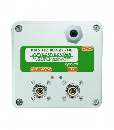
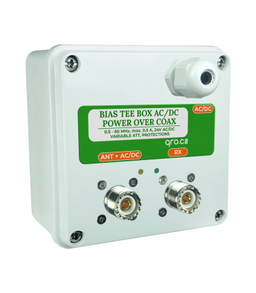
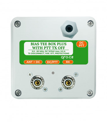
A bias tee for DC voltage with PTT TX OFF
select the delivery location, based on the selection, the sales prices and delivery costs will be recalculated

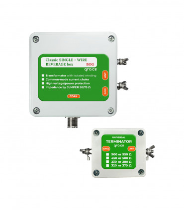
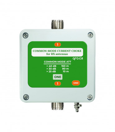
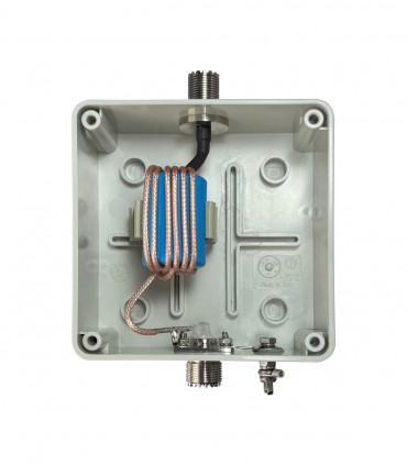
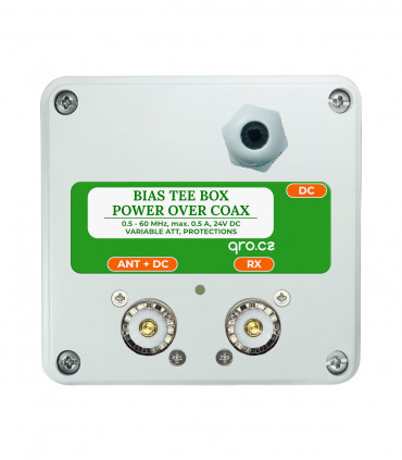
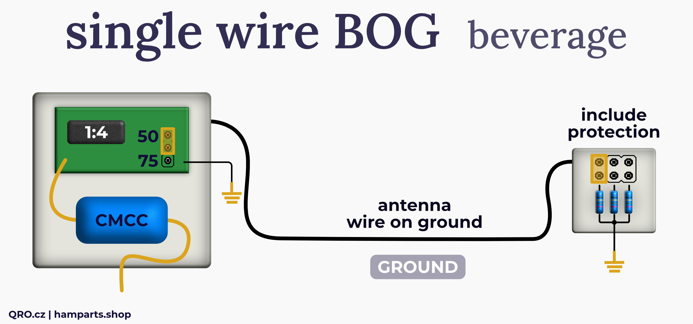
This manual explains how to use the antenna and configure phasing options within an array system. The antenna kit includes an impedance transformer with two selectable conversion ratios and a universal terminating resistor. Surge and current protection, a common-mode filter, and the ability to invert the output signal phase are also integrated.
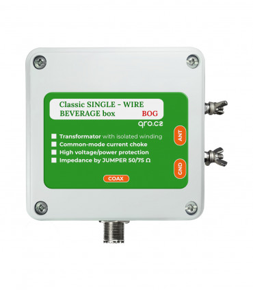
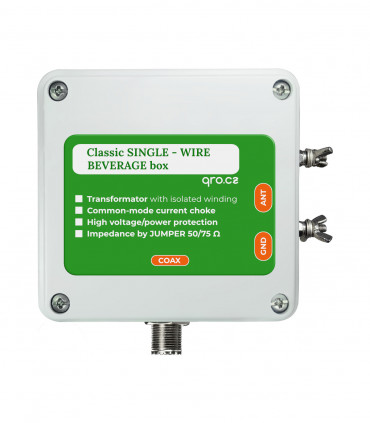
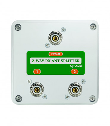
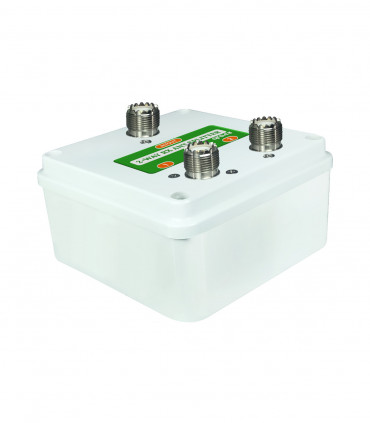
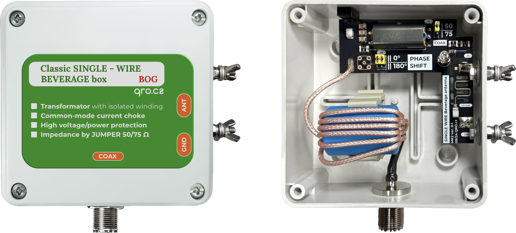
Feeder Box
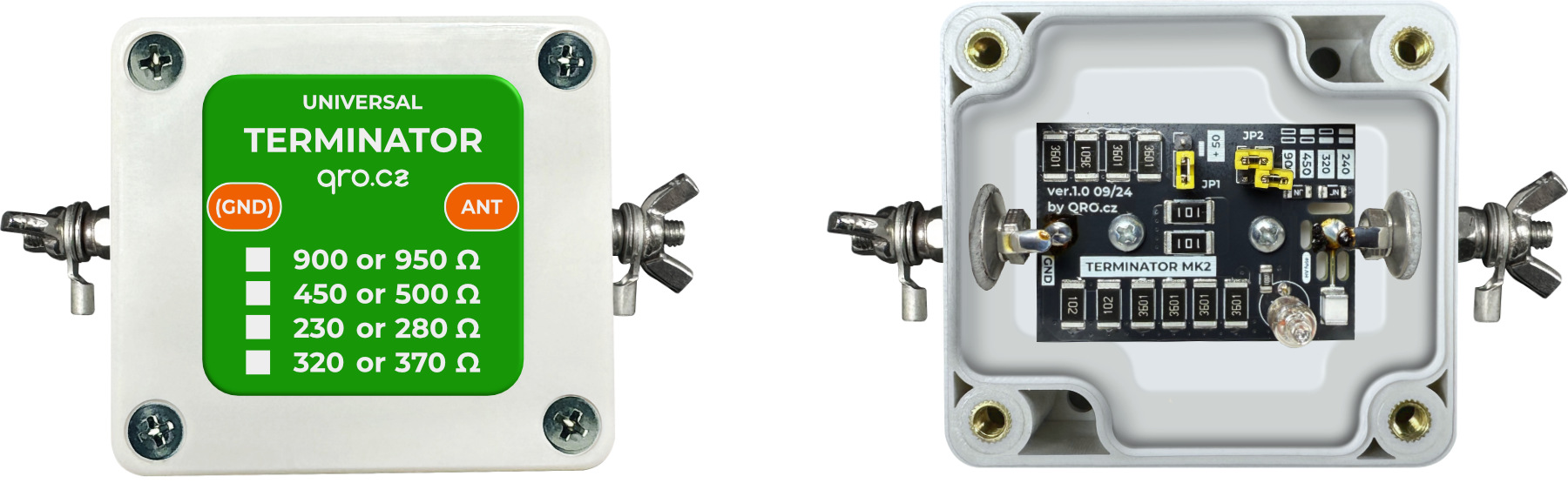
Terminator Box
Jumpers settings
Antenna lenght
Antenna testing
RX Arrays
FAQ
Product details
This part of the set includes input surge protectors, a SuperFuse to disconnect the circuit at currents greater than 100mA, an isolation transformer with two conversion ratios, and an output common-mode filter.
It is a universal termination resistor. Thanks to the jumpers you can set eight different values. Surge and current protection are again included. Terminator is designed for 4 W of RF power; resistors can handle max 8W - depends on resistance (JP2).
For BOG use 240 to 370 Ohm to find the best SWR.
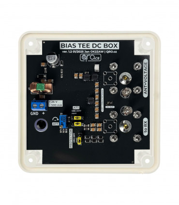
Using the jumpers in both boxes it is possible to change the parameters. There is the information for each option.
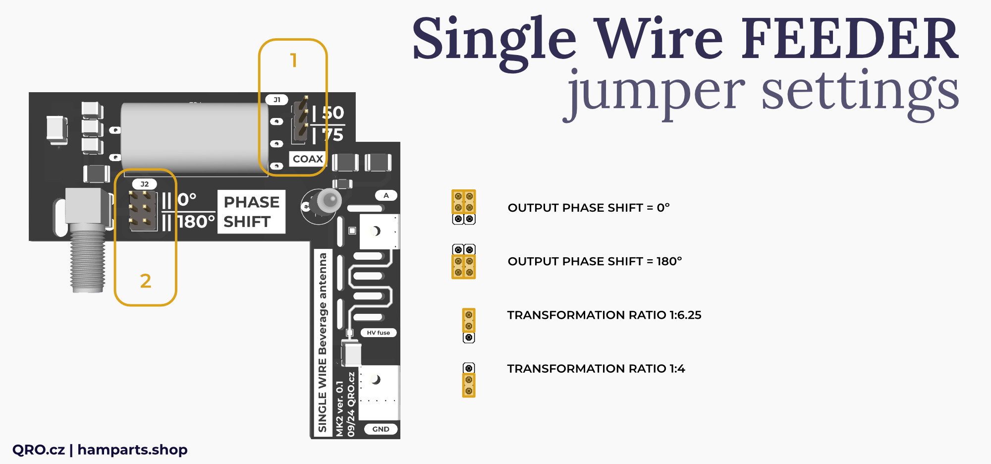
- Transformation ratio: 50 = 1:6.25 and 75 = 1:4
- Output Phase. For antenna array, more in arrays info.
Impedance ration example:
- Jumper in position 50 has ratio 1:6.25. It means when you use 50 Ohm coax cable, antenna impedance is 6.25 x 50 = 312.5 Ohm
- Jumper is position 75 has ratio 1:4. For 50 Ohm coax, antenna impedance is 200 Ohm
- Or 75 Ohm coax is: 1:6.25 = 470 and 1:4 is 300 Ohm.
DO NOT FORGET - There are inherent losses in the antenna’s ground connection. The ground rod and installed radials typically contribute between 20 and 70 Ohms of loss on each side. These losses depend on soil conductivity, the length of the ground rod, the number of radials, and similar factors. They must be added to the value of the terminating resistor and taken into account when designing the antenna system.
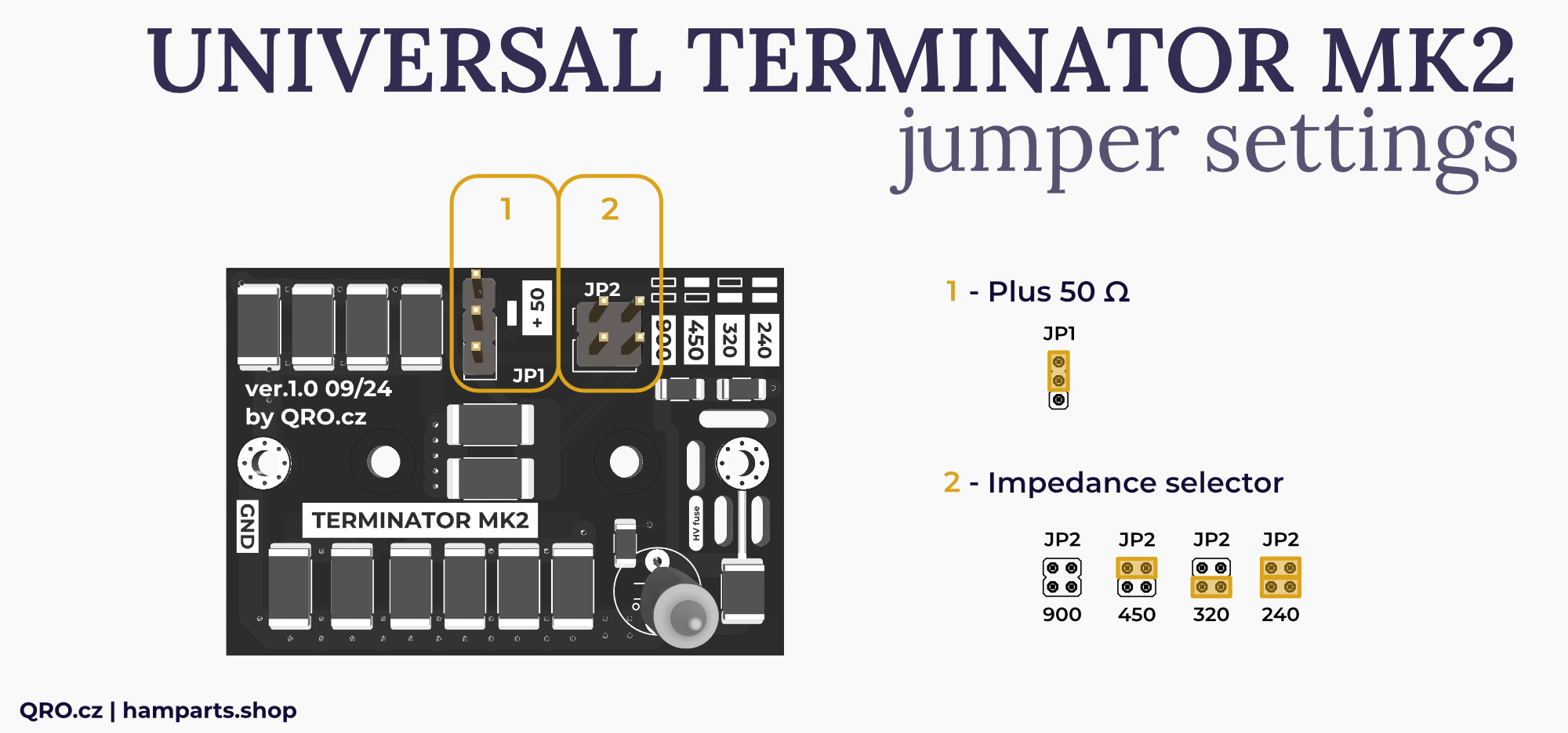
- Adds +50 Ohm to the resistance of JP2 when the jumper is in the upper position
- Select resistence: 240, 320, 450, 900 Ohm.
Possible resistances are: 240, 290, 320, 370, 450, 500, 900, 950 Ohm.
The Beverage on Ground (BOG) antenna typically measures between 0.5 and 1.0 wavelengths for the desired operating band, though it can be shorter — around 60 to 90 meters (200–300 feet) for the 160 m band. This is due to its lower velocity factor (approximately 50–60%) compared to an elevated Beverage antenna. The optimal length is a balance between directivity and ground losses: shorter antennas offer reduced directionality, while longer ones may experience increased signal attenuation.
Velocity Factor: The wire's proximity to the ground slows the wave, so a 60m BOG can have the electrical length of a much longer elevated antenna.
Typical Length Recommendations:
- For 160m (1.8 MHz): A common starting point is 60 to 90 meters (200 to 300 feet).
- Shorter BOGs: Can work, but directivity is reduced, especially below 60m for 160m.
- Longer BOGs: May increase ground losses, diminishing overall performance.
Practical Considerations:
- Height: Place the BOG wire just above the grass, ideally 2-10 cm (1-4 inches)high, not directly on the ground.
- Termination: The far end of the wire is terminated with a resistor (around 240-300 ohms) connected to a ground rod.
- Directionality: Directivity is improved by keeping the antenna straight and at a low height.
You can use an antenna analyser or VNA to measure the SWR of the antenna. By varying the end load resistor and possibly the transformer ratio, you can achieve as flat SWR as possible in the 2–8 MHz range. The SWR is typically within 1:1.3 for the 50 ohm version.
In this article you will find notes and comparison of antenna systems using our N-way splitters and Single Wire Beverage MK2 set. Please, read our technical article Phasing Beverage antennas into the array.
FAQ
Product details
Single wire box assembled and tested or all parts for KIT version
Single wire terminator assembled and tested or all parts for KIT version
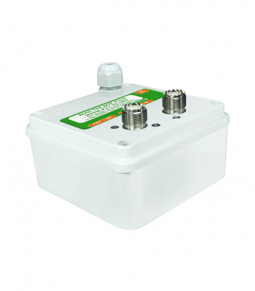
| Box dimensions (mm) | 100x100x50 - PU box IP56 |
|---|---|
| Box dimensions (mm) | 65x58x35 - PU box IP56 |
| Weight brutto (kg) | 0.44 kg |
Ing. Jan Šustr
ID 05476356, VAT CZ8407024780
Palachova 1777/7, 591 01 Žďár nad Sázavou, Czech republic, Europe
Please also read general instructions before handling the product.
ID 05476356, VAT CZ8407024780
Palachova 1777/7, 591 01 Žďár nad Sázavou, Czech republic, Europe
is compatible with the relevant Union harmonisation legislation directives:
EMC Directive 2014/30/EU
ČSN EN 61000-6-3 ed. 2
ČSN EN 61000-6-1 ed. 2 (333432)
On behalf of Ing. Jan Šustr (QRO.cz)
Ing. Jan Šustr, CEO
10th November 2025
Please sign in first.
Sign inCreate a free account to save loved items.
Sign inCreate a free account to use wishlists.
Sign in