Manual for Single Wire Beverage MK2 RX antenna. Describes the use and phasing options for the array. Antenna set includes impedance transformer with two conversion ratios and universal load resistor - terminator. Surge and current protection, common-mode filter and output signal phase change capability are included.
Jump to
Feeder Box
Terminator Box
Jumpers settings
Antenna testing
RX Arrays
FAQ
Product details
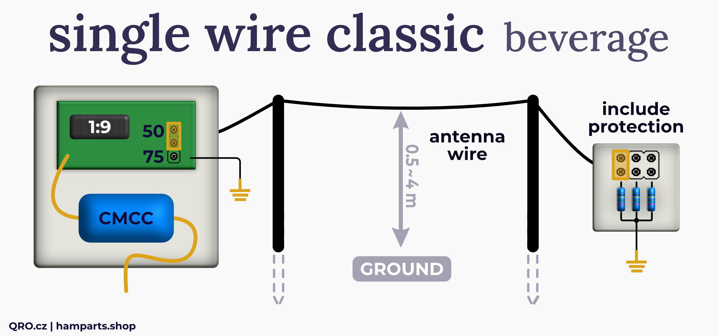
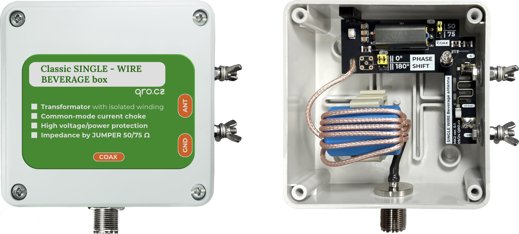
Feeder Box
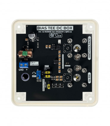
This part of the set includes input surge protectors, a SuperFuse to disconnect the circuit at currents greater than 100mA, an isolation transformer with two conversion ratios, and an output common-mode filter.
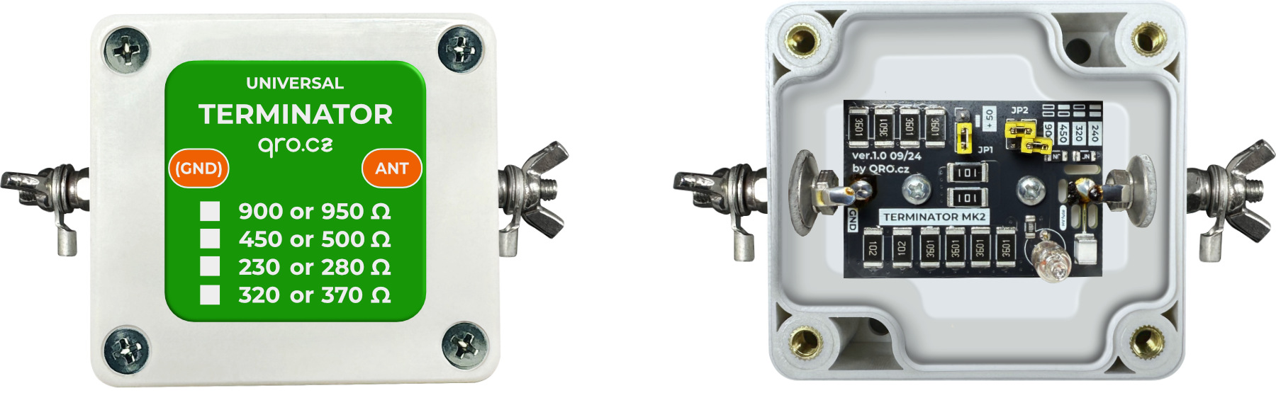
Terminator Box
It is a universal termination resistor. Thanks to the jumpers you can set eight different values. Surge and current protection are again included. Terminator is designed for 4 W of RF power; resistors can handle max 8W - depends on resistance (JP2).
Jumpers settings
Using the jumpers in both boxes it is possible to change the parameters. There is the information for each option.
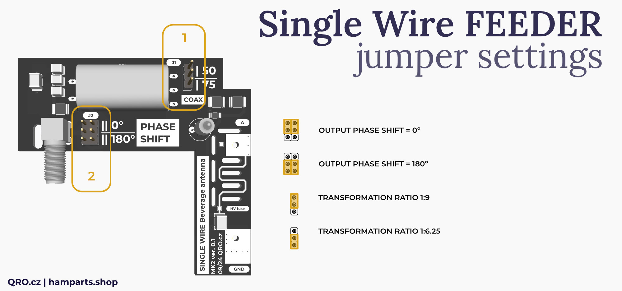
1. Jumper J1
- Transformation ratio: 50 = 1:9, 75 = 1:6.25
2. Jumper J2
- Output Phase. For antenna array, more in arrays info.
Impedance ration example:
- Jumper in position 50 has ratio 1:9. It means when you use 50 Ohm coax cable, antenna impedance is 9 x 50 = 450 Ohm
- Jumper is position 75 has ratio 1:6.25. For 50 Ohm coax, antenna impedance is 312 Ohm
- Or position 75, when antenna is 470 Ohm, output at coax side is 75 Ohm
DO NOT FORGET - there are considerable losses in the connection to the ground. The ground rod and the laid radilas will have a loss of 20 to 70 Ohms on each side. The losses are proportional to the quality of the ground, the length of the ground rod, the number of radials, etc. These losses must be added to the terminating resistor and must be accounted for.
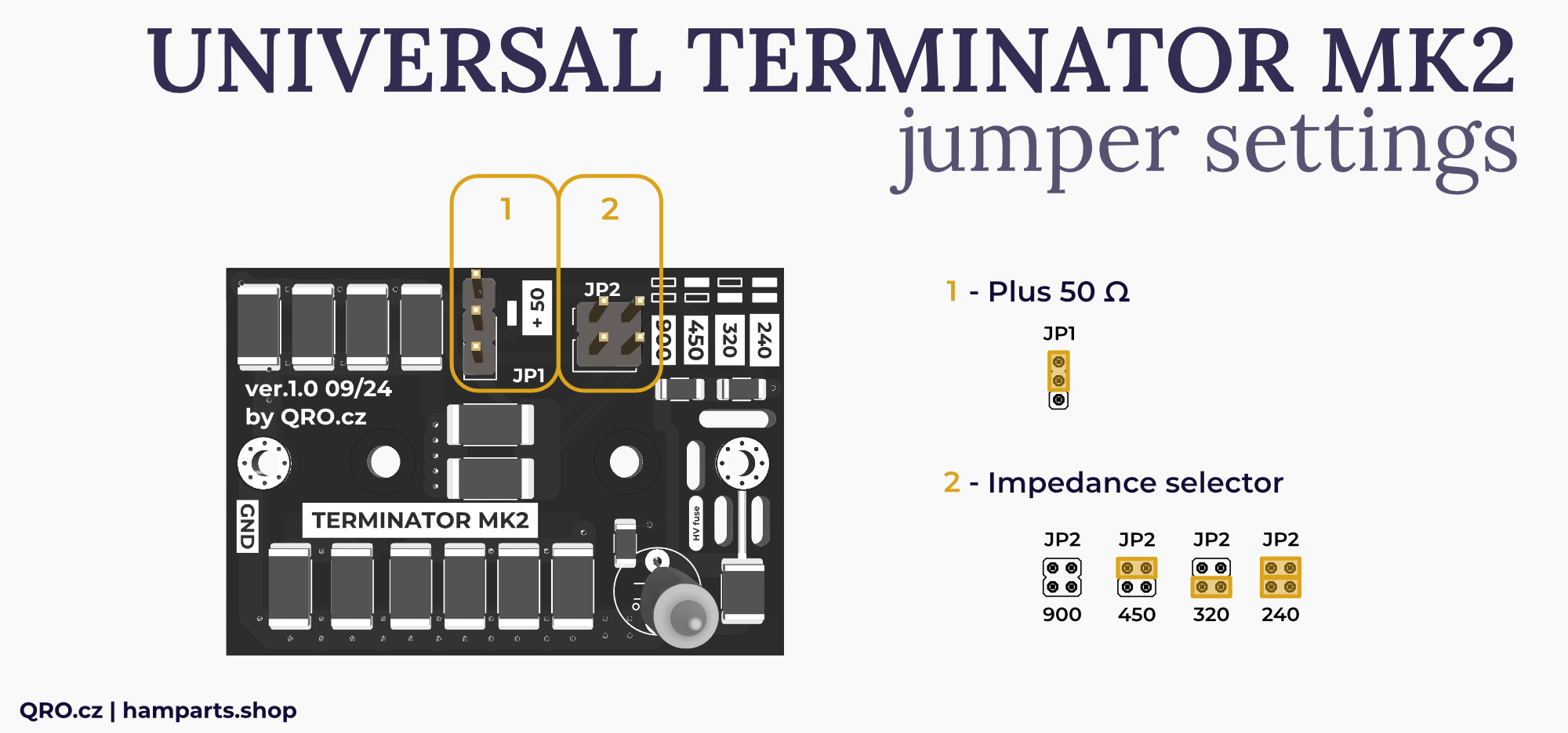
1. Jumper J1
- Adds +50 Ohm to the resistance of JP2 when the jumper is in the upper position
2. Jumper J2
- Select resistence: 240, 320, 450, 900 Ohm.
Possible resistances are: 240, 290, 320, 370, 450, 500, 900, 950 Ohm.
Antenna testing
You can use an antenna analyser or VNA to measure the SWR of the antenna. By varying the end load resistor and possibly the transformer ratio, you can achieve as flat SWR as possible in the 2–8 MHz range. The SWR is typically within 1:1.3 for the 50 ohm version.
RX arrays
In this article you will find notes and comparison of antenna systems using our N-way splitters and Single Wire Beverage MK2 set. Please, read our technical article Phasing Beverage antennas into the array.