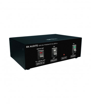
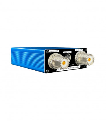
Receiving antennas open a new DX world. To connect and experiment with RX antennas, you need to figure out how to connect such an antenna to the TRX. The more expensive TRXs have a direct RX ANT input. Smaller TRXs do not provide this option. One option is some more complex RX system that also has RX ANT switching. The other option is this small box that allows you to connect RX ANT to the TRX via proper protections, switching control during transmitting, manual switching between RX and TX/RX antenna, PTT splitter, etc.
PTT can also be connected to YAESU TRX that do not have RCA connector. With the mini DIN TUNER connector you get the PTT signal and this box allows you to connect other external devices (PA) to the classic RCA connector (PTT OUT).
Jump to
Parameters
Blog diagram
Connection
Connection examples
LED indication
RX ANT control
Measurements
Product details
Parameters
Frequency range 0.1 MHz to 30 MHz
RF power up to 250 W
RX ANT input high pass 100 kHz
RX ANT GDT and Neon lamp surge protection
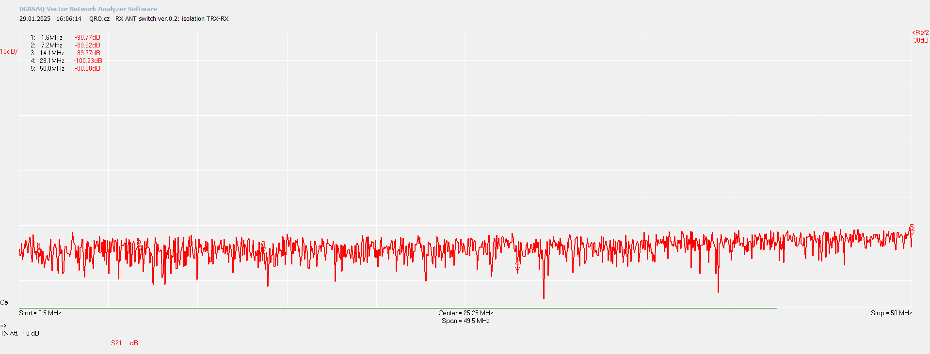
High isolation: TRX - RX ANT over 100 dB
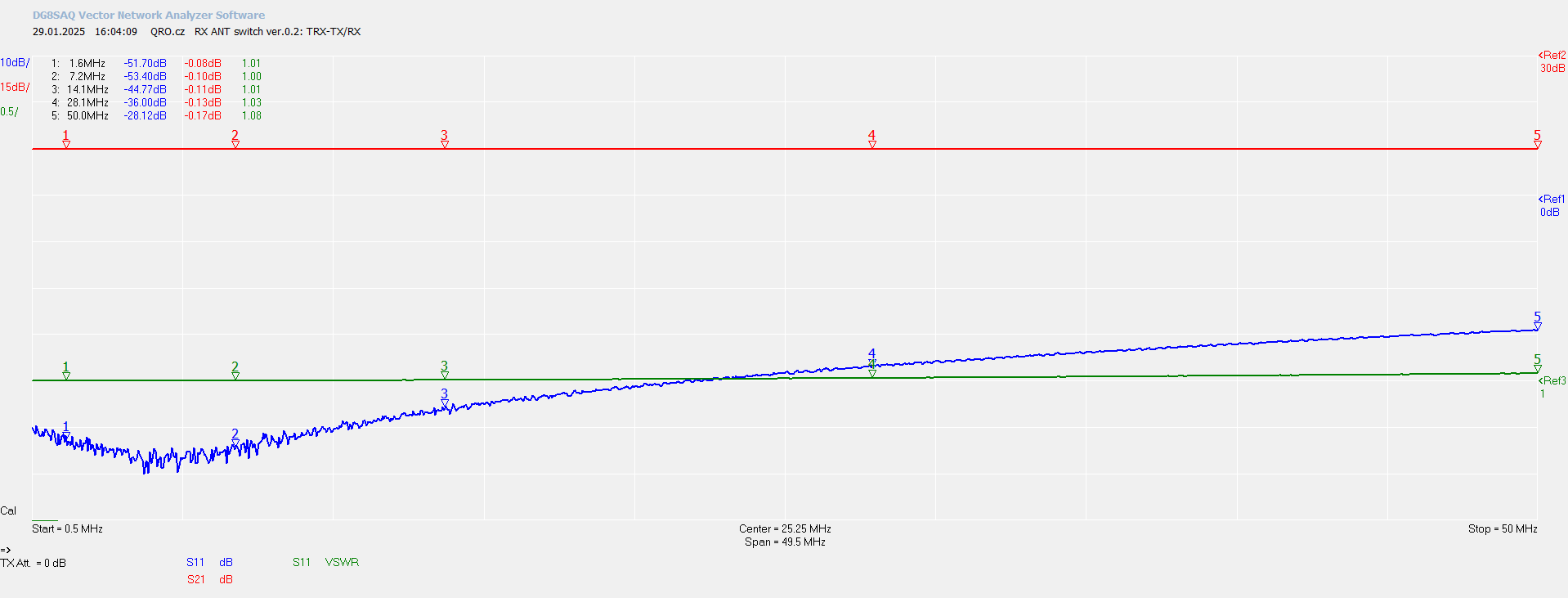
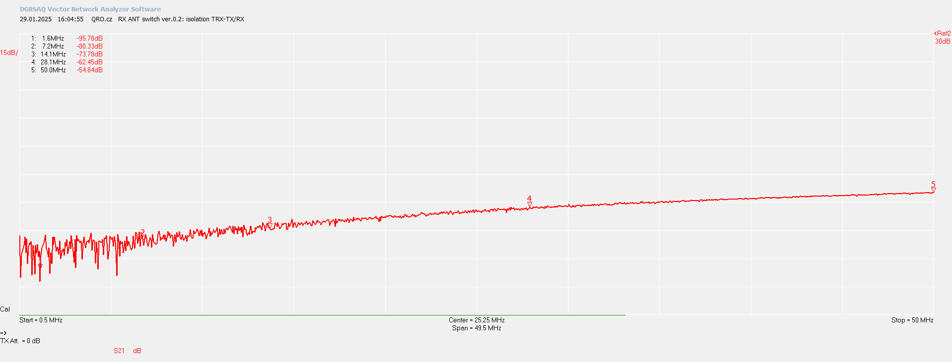
High isolation: TRX - TX ANT over 80 dB @ 7 MHz
Low insertion loss: 0.8 dB @ 7 MHz
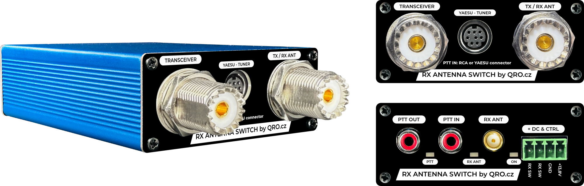
RX ANT connector: SMA
TRX and TX/RX ANT: SO-239 female
DC IN 13.8 V and 0.3 A
DC IN: green connector or YAESU TUNER
RX/TX controlled by PTT
PTT IN: RCA and mini DIN
PTT OUT: RCA
PTT IN current typ. 15 mA
PTT OUT: FET with 0.5 A polyfuse
PTT OUT: max. 60 V DC open
PTT IN and OUT: optocoupler isolators
LED: ON (Y), RX ANT (G), PTT (R)
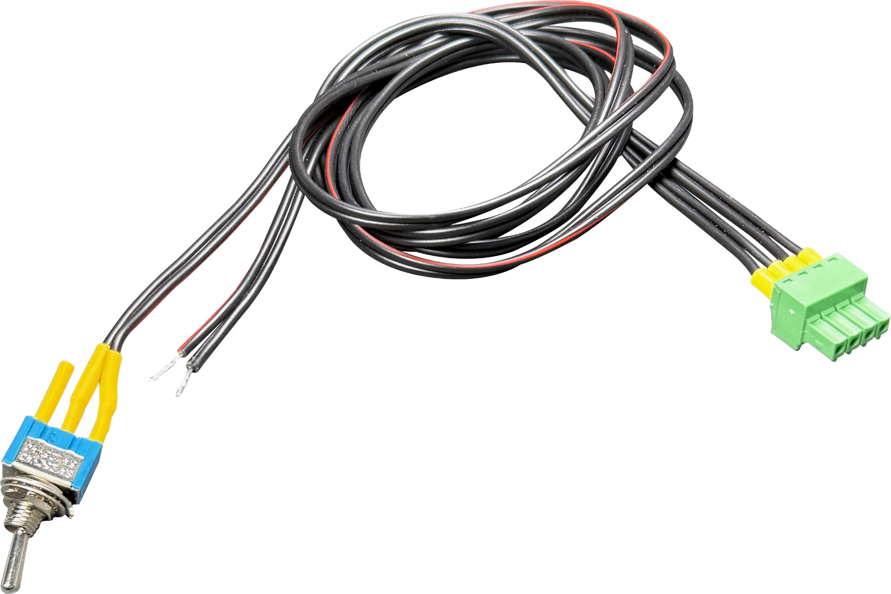
Control switch: small toggle switch
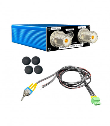
1m long cables for DC and toggle switch
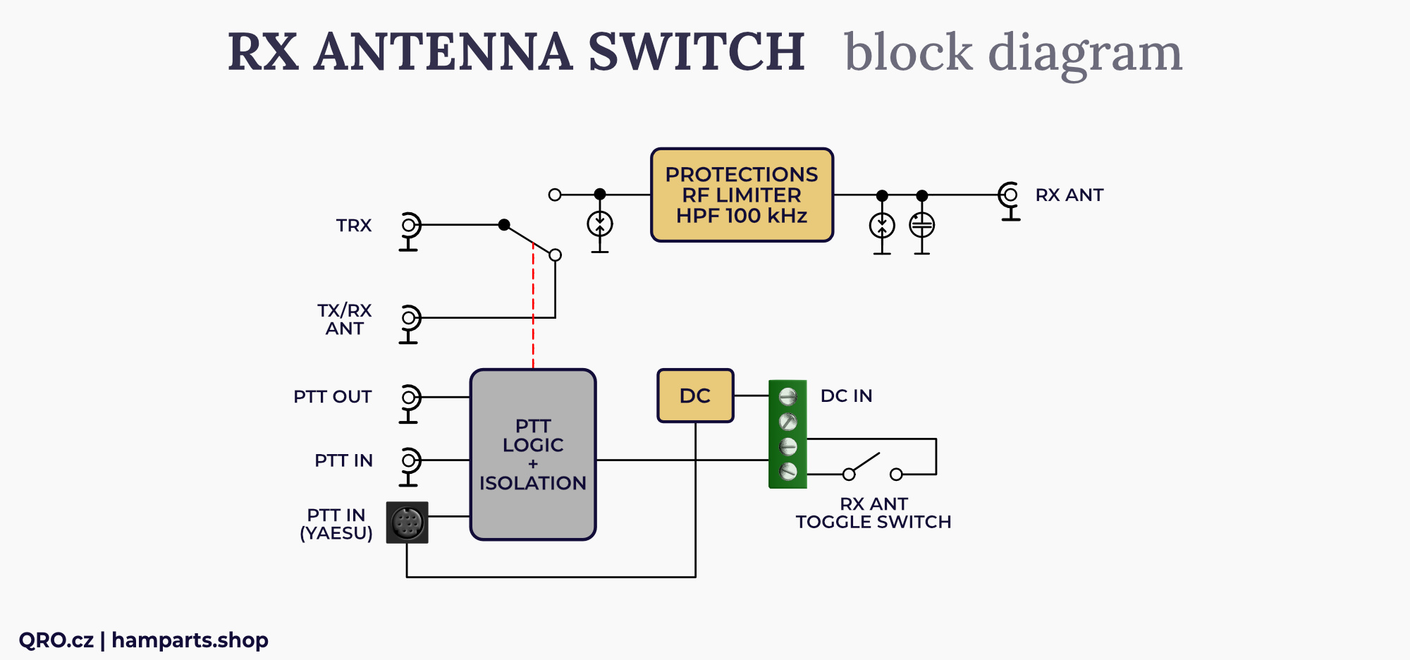
Block diagram
There is the block diagram of the switch. The transmit signal is switched by a double contact power relay, due to the relay configuration minimal crosstalk from the TX antenna is achieved when using the RX ANT.
The PTT includes optical decoupling. An RCA connector labeled PTT IN or a mini DIN YAESU labeled TUNER can be used as the PTT IN signal. The box also contains PTT OUT. This is not delayed in any way, the box does not contain a sequencer. PTT OUT is via a FET transistor with a reversible fuse and 0.5A protection.
Power to the switch can be supplied from the YAESU TRX using a mini DIN cable or via a two-line connection on the green connector.
The RX ANT can be selected using the toggle switch. This is at the end of a 1m long cable and can be positioned to your liking.
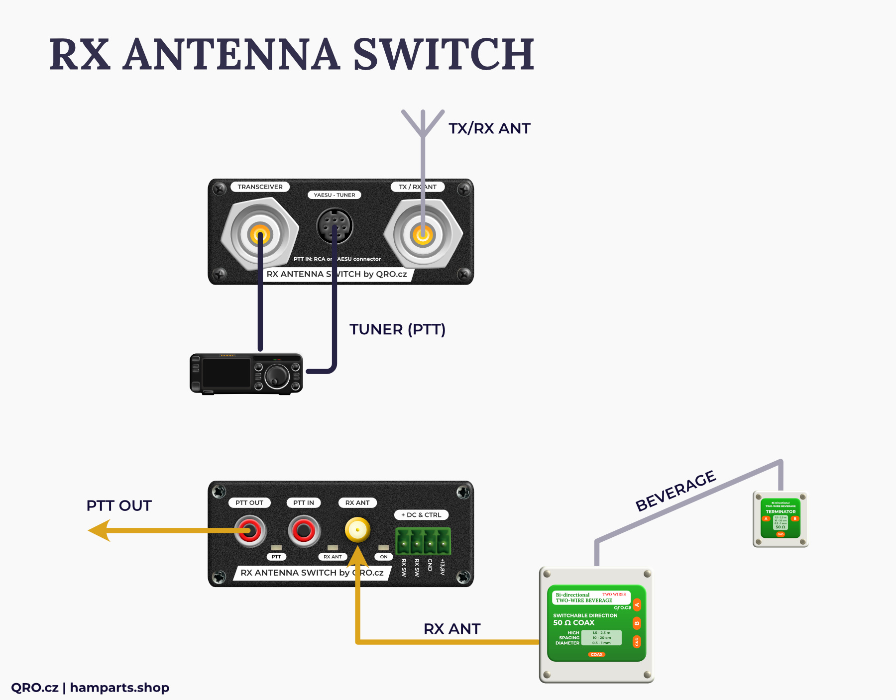
Connection
This is an example of linking with YAESU. The power supply and PTT signal is taken from the TUNER mini DIN connector. PTT OUT can be used to connect a PA.
Connection examples
Example with Icom IC-7300
The Icom IC-7300 is a very popular compact TRX. However, if you want to connect an RX antenna, you must use an external switch - Icom does not include an RX ANT input. With our RX ANTENNA Switch you can conveniently add an RX antenna to your IC-7300. You can switch between TX and RX antenna, use the protection elements in the switch and thanks to the built-in PTT splitter you won't lose the PTT output for the PA.
Here is an example of connecting:
- Connect RCA cable from Icom rear panel - RCA jack SEND to RX ANTENNA Switch (RXAS) connector PTT IN
- PTT OUT jack at RXAS can be used for Power amplifier PTT etc.
- Connect coax cable from TRX ANT port to TRANSCEIVER connector at RXAS
- Connect TX/RX antenna or PA to TX/RX ANT port at RXAS
- Connect RX antenna to RX ANT SMA at RXAS
- Connect 13.8 V to RXAS
- Use small switch to select TX or RX only antenna
- Check if PTT works - with low power trasmit with Icom and check if LED PTT is red on RXAS. If not, check wiring again.
- RXAS must be switched ON (connected to 13.8 V) for the switching and PTT circuits to work!

Example with YAESU FT-DX10
Like the IC-7300, the YAESU FT-DX10 is a very popular TRX. Thanks to its design, this small radio is very durable and can withstand even the toughest deployments (e.g. M/M TX on CN3A). The lack of RX ANT input is also a disadvantage. The solution is again an external switch. Preferably our RX ANTENNA Switch (RXAS) can be used. Connection to YAESU is possible via RCA connector or mini DIN 8 ACC connector for TUNER. With this connection, the RXAS can be powered directly from the TRX. The PTT OUT RCA jack on the RXAS can be used to connect a PA. If you need the ACC TUNER jack on the YAESU to connect to a tuner or PA, you will have the problem of no PTT signal for the RXAS. This can be solved by inserting our product - YAESU PTT splitter

Here is an example of connecting:
- Connect mini DIN 8 cable from TUNER at FT-DX10 to YAESU TUNER mini DIN 8 at RX ANTENNA Switch (RXAS)
- PTT OUT jack at RXAS can be used for Power amplifier PTT etc.
- Connect coax cable from TRX ANT port to TRANSCEIVER connector at RXAS
- Connect TX/RX antenna or PA to TX/RX ANT port at RXAS
- Connect RX antenna to RX ANT SMA at RXAS
- Use small switch to select TX or RX only antenna
- Check if PTT works - with low power transmit with YAESU and check if LED PTT is red on RXAS. If not, check wiring again.
- As the RXAS has 13.8 V from TRX over mini DIN cable, you do not need to connect extra 13.8 V to green connector
If you need to use TUNER connector at YAESU
If you have a busy TUNER connector on the TRX, you have a problem with a missing PTT signal from the TRX. You can solve this by adding our YAESU PTT SPLITTER. Then you insert this box between the TRX and the device that is connected to the TUNER connector (Tuner, Power Amplifier...) Connection is:
- TUNER at TRX to TUNER TRX mini DIN at YAESU PTT SPLITTER (YPS)
- From YPS TUNER to the device which was connected to TUNER at TRX before
- PTT OUT at YPS to RX ANTENNA Switch (RXAS) PTT IN
- There are now to extra PTT OUT for another devices one at YPS, second at RXAS
- Connect coax cable from TRX ANT port to TRANSCEIVER connector at RXAS
- Connect TX/RX antenna or PA to TX/RX ANT port at RXAS
- Connect RX antenna to RX ANT SMA at RXAS
- Use small switch to select TX or RX only antenna
- Check if PTT works – with low power trasmit with YAESU and check if LED PTT is red on RXAS. If not, check wiring again.
- As the RXAS and YPS have 13.8 V from TRX over mini DIN cable, you do not need to connect extra 13.8 V to green connector
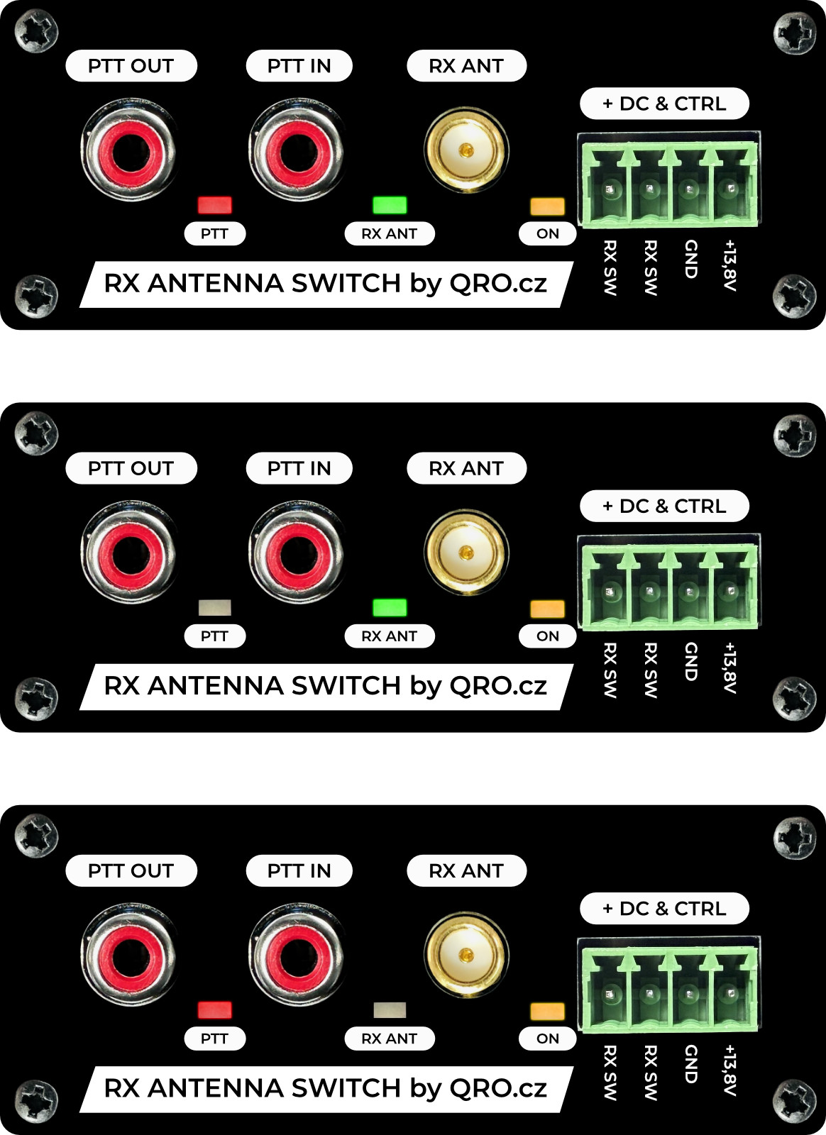
LED indication
Yellow LED ON - DC power ON indicator
Green LED RX ANT - RX ANT is selected
Red LED PTT - Transmitting, RX ANT disconnected, TRX connected to TX/RX ANT
RX ANT control
When the box is turned off the TRX is connected to the TX/RX port. It is possible to listen and transmit (to, from TX/RX ANT), but PTT OUT does not work. When DC power is connected, the box is controlled by two signals. One is PTT, where when transmitting the TRX is always connected to the TX/RX connector. The other control is on the green screw terminal. The connected switch allows you to select between RX ANT and TX/RX ANT inputs. This switches the signal source for the receiver. Transmission is always to the TX/RX port.
This control is possible by using the supplied small toggle switch or by replacing it with a larger one or by using a relay contact - for example Remote Control
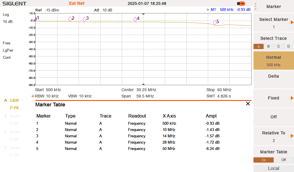
Measurements
SWR TRX - TX ANT
Isolation TRX - TX ANT while using RX ANT
Isolation TRX to RX ANT while transmitting


