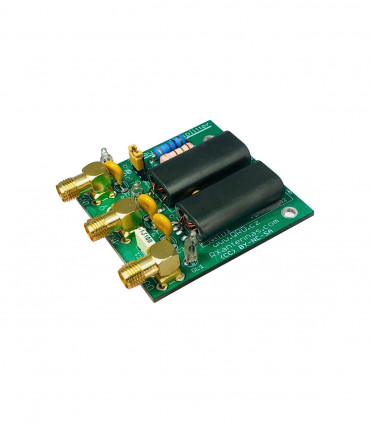
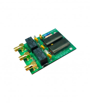
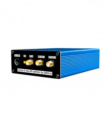
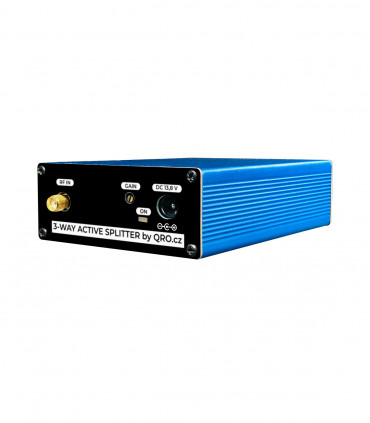
2-way active splitter manual
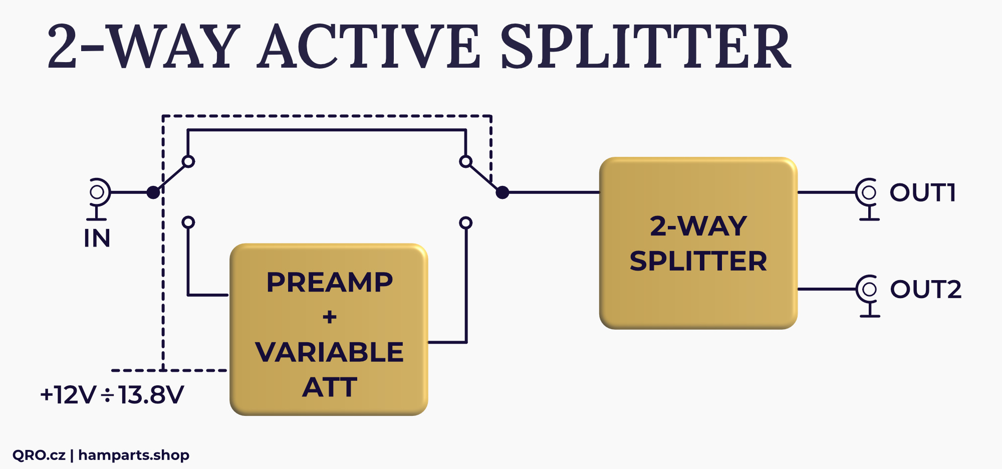
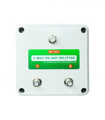
The splitter or combiner is a very useful device. It can provide equal voltages, equal current, or equal power to matched or unmatched loads. This is active splitter version where you can switch ON high IP, low noise preamplifier and eliminate insertion loss of the splitter. Gain can be set as you need by the Variable ATT at PCB.
NOTE: This HW is designed only for RX line. There are some more high current and voltage protections on all ports. Both impedances 50 or 75 Ohm can be selected by the jumper.
Jump to
Applications
Splitter
Schematic
PCB
Tune and test points
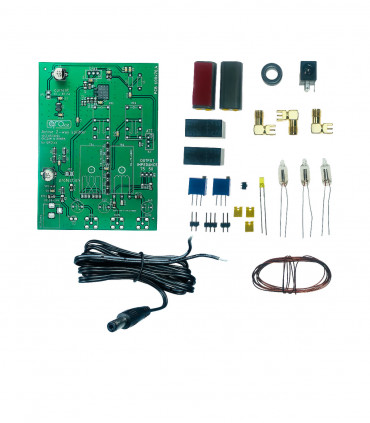
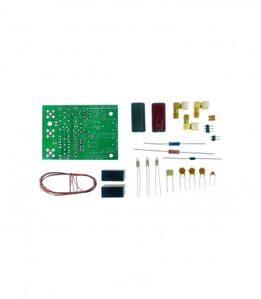
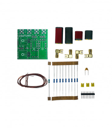
KIT Assembling
Part list
Transformers
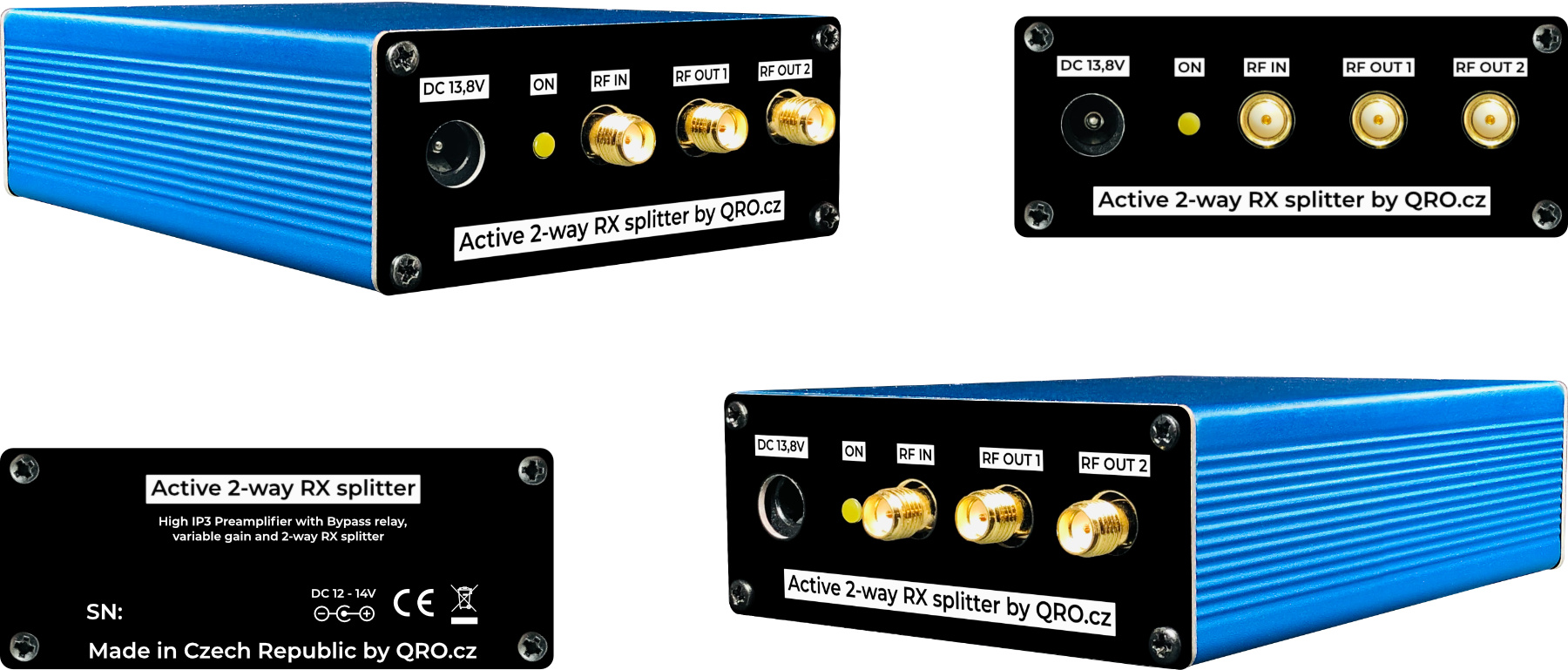
Product details
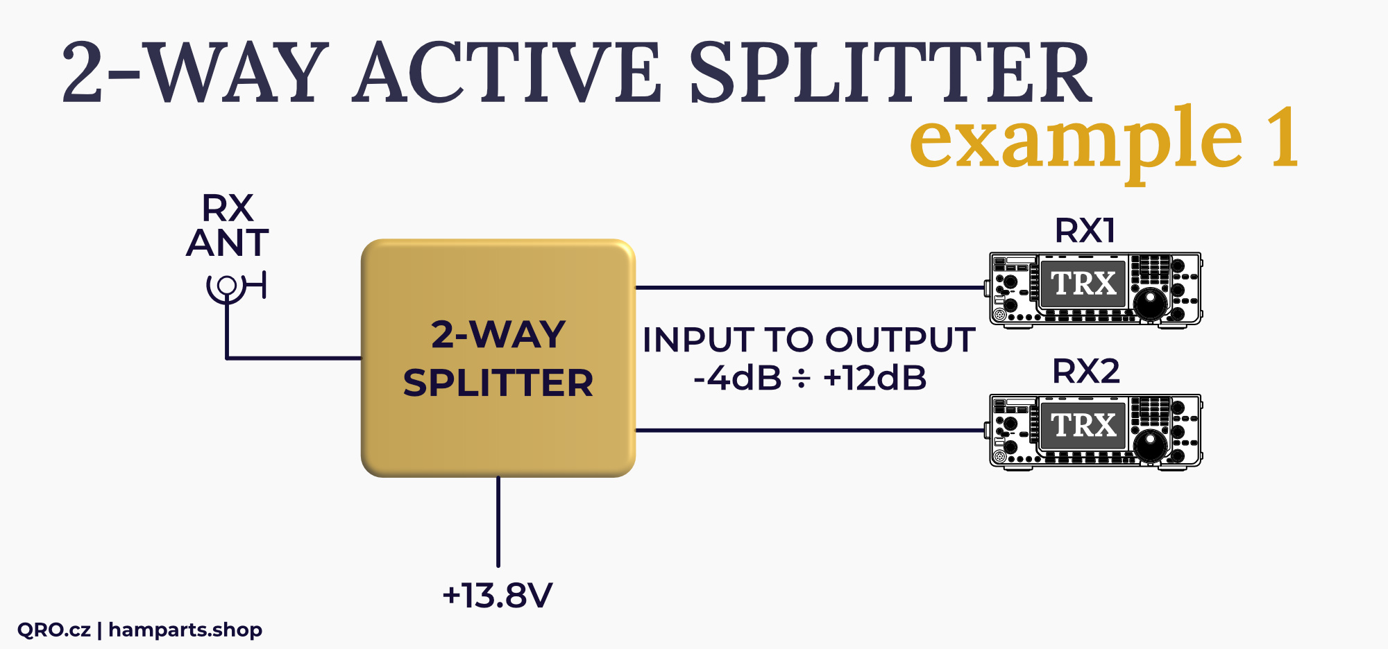
Applications
Only two way splitter without preamplifier
Example fot two RX with preamplifier
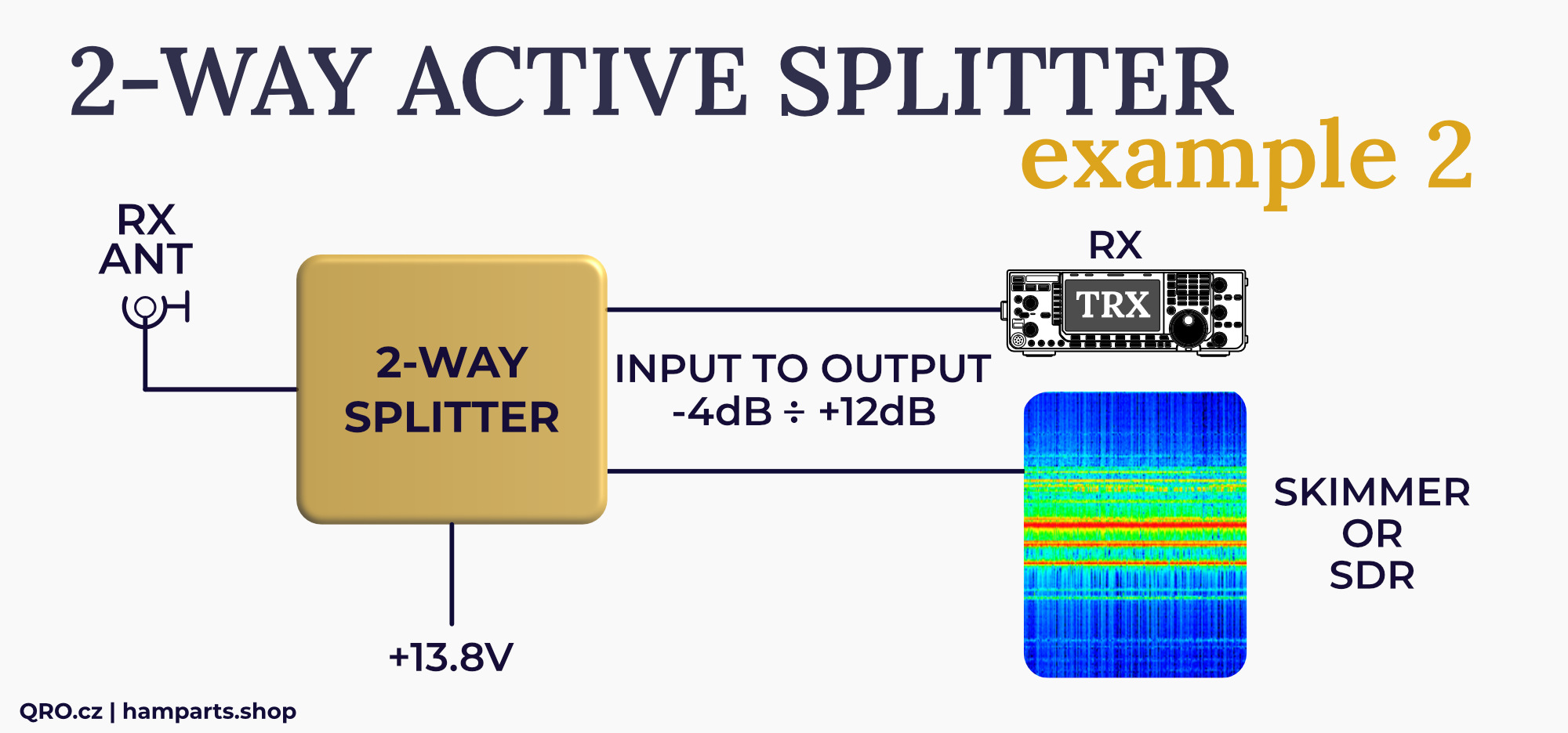
Example for RX and SDR with preamplifier
Splitter
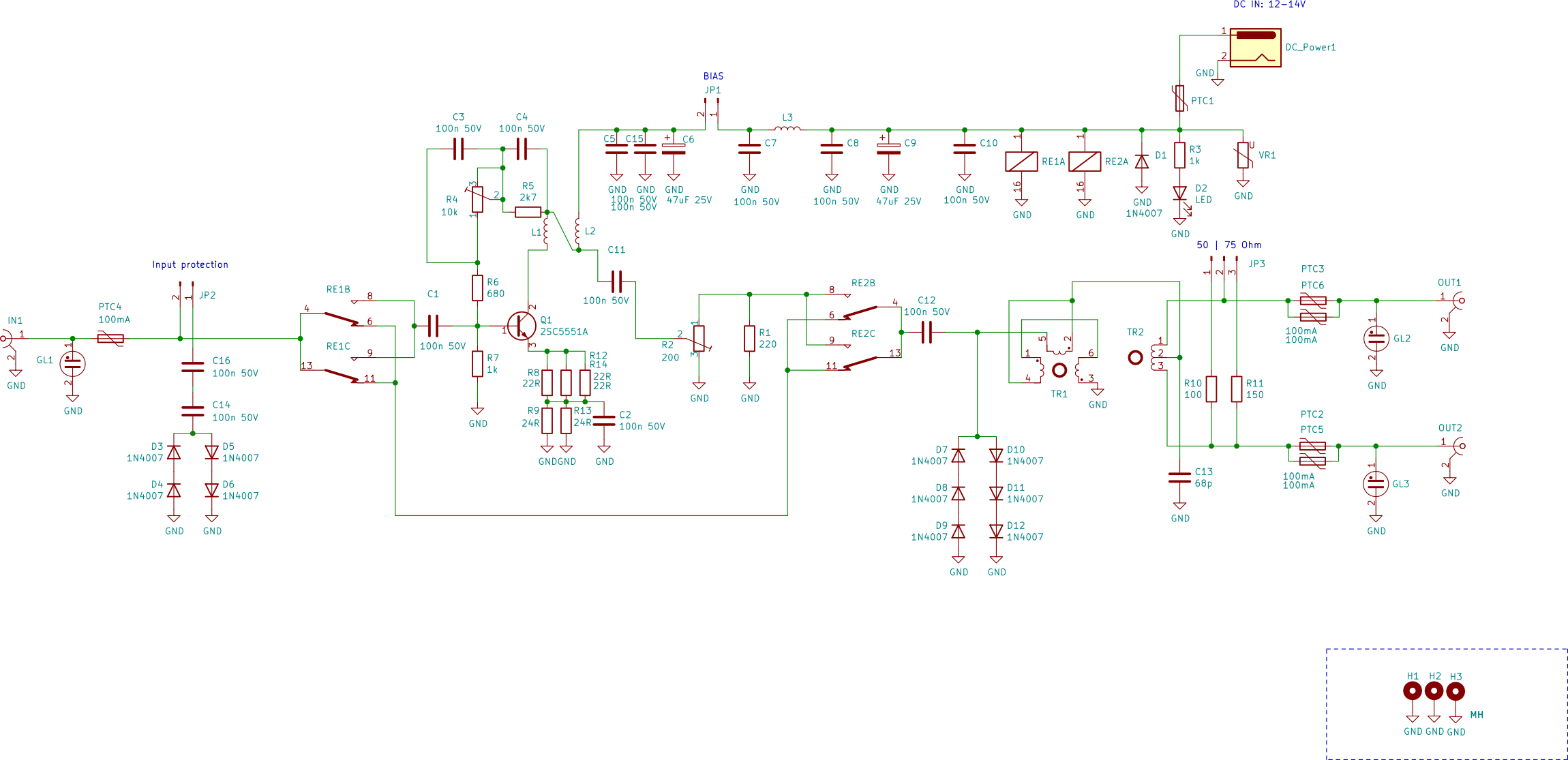
Schematic
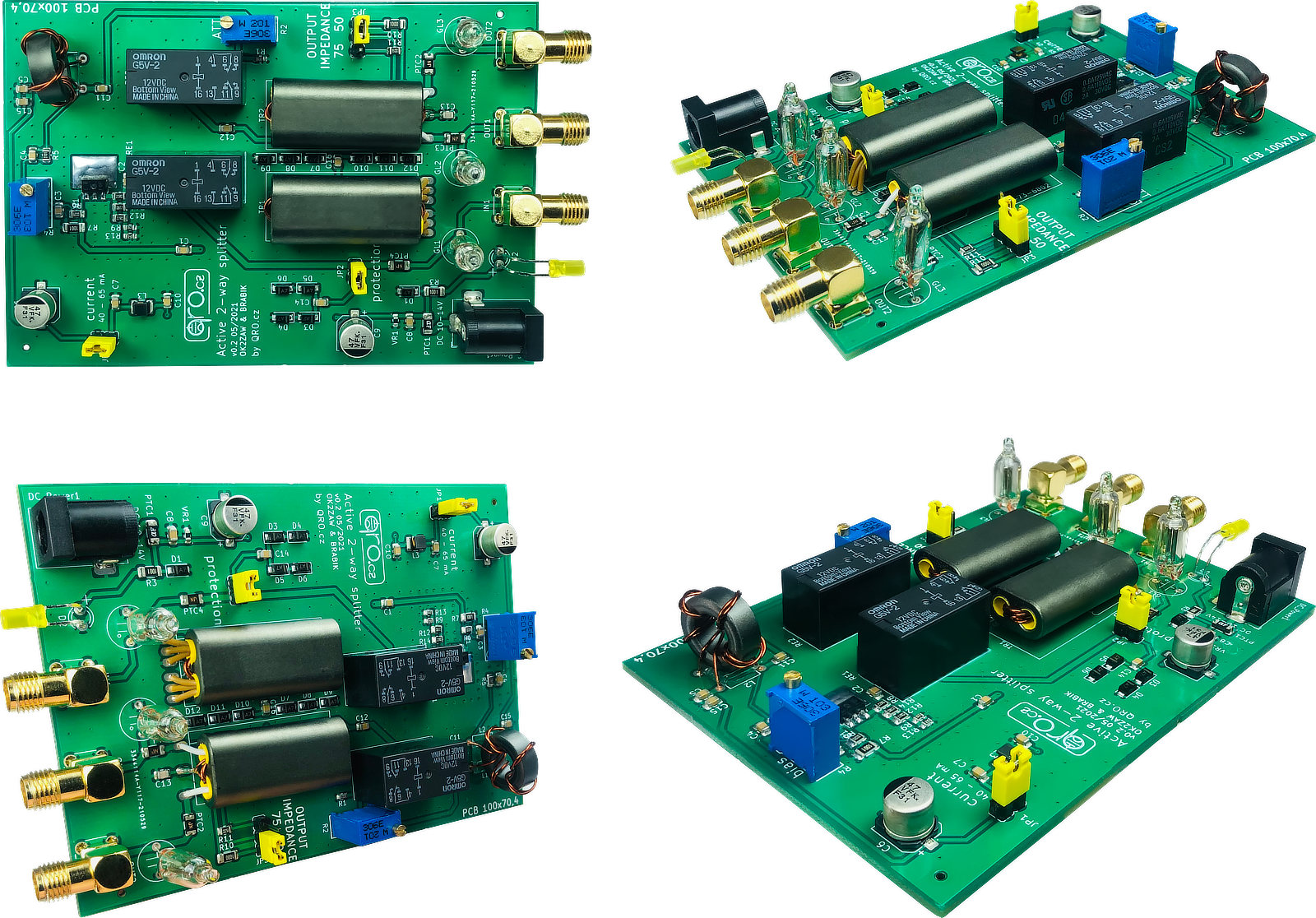
PCB
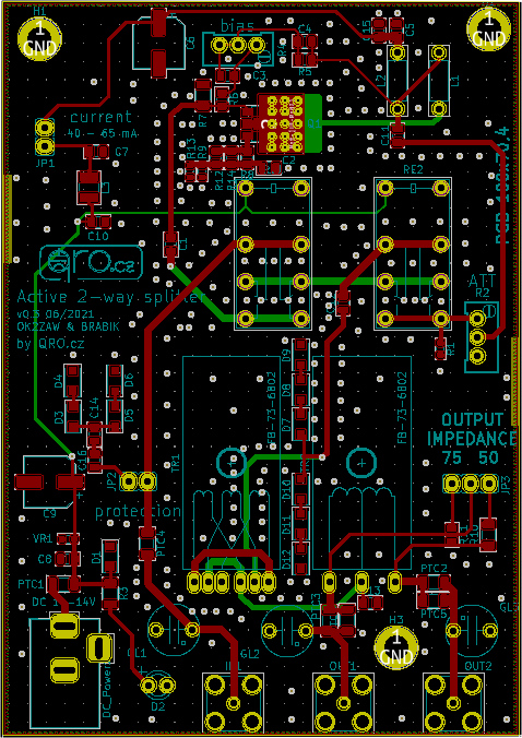
Tune and test points
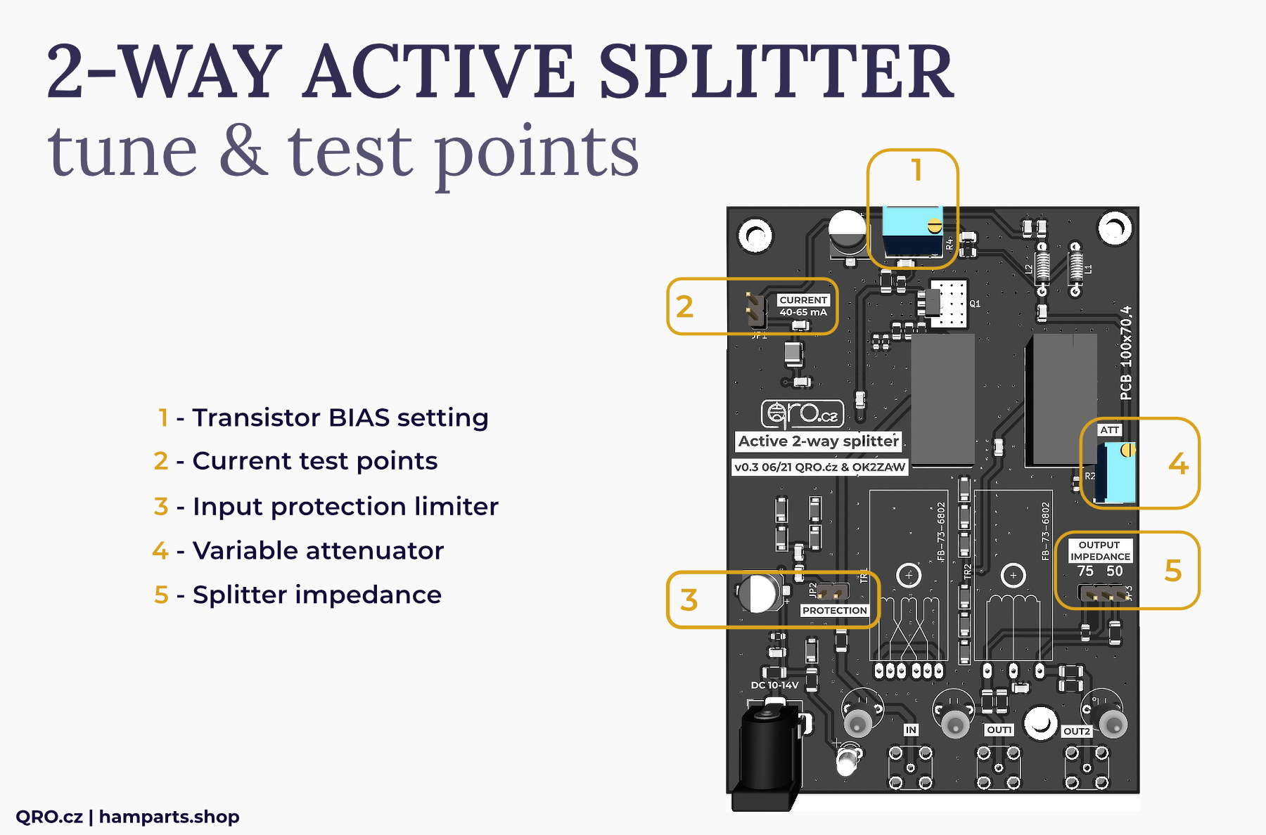
There are two trimmer resistors which allow you to set gain (variable output attenuator) and bias of transistor. Bias is preset to 40 mA at 13.8 V. Jumper with the test points for transistor current check and jumpers for splitter impedance switching between 75 and 50 Ohm.
1. Transistor BIAS setting
- this is trimmer (BIAS R4) which sets transistor bias current
- higher current means higher IP3
- recommended is 40 to 50 mA - higher currents need better cooling
- with bias current around 15 mA, the noise figure of the preamplifier is around 1
- for setting this bias current open jumper JP1 and measure it there
2. Current test points
- remove jumper (JP1)
- connect mA meter there (200 mA scale is fine)
- connect supply voltage
- turn the resistor trimmer (BIAS R4) and set bias current you want
- then connect jumper short back again
3. Input protection limiter
- this is diode limiter
- limites input signals to around 17 dBm
- together with PTC fuse works as high current protection
- diode limiter can give rise to the generation of harmonic and intermodulation distortion
4. Variable attenuator
- by this resistor trimmer you can set preamplifier gain as you need
5. Splitter impedance
- by this jumper JP3 you can set splitter impedance 50 or 75 Ohm
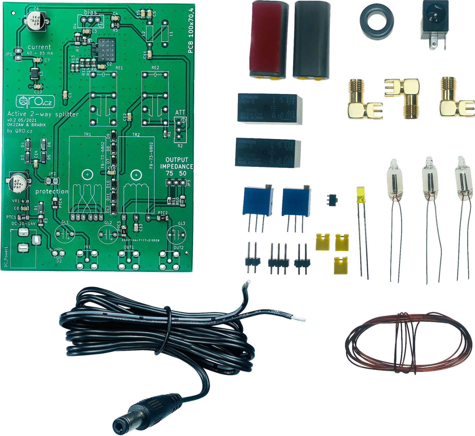
KIT Assembling
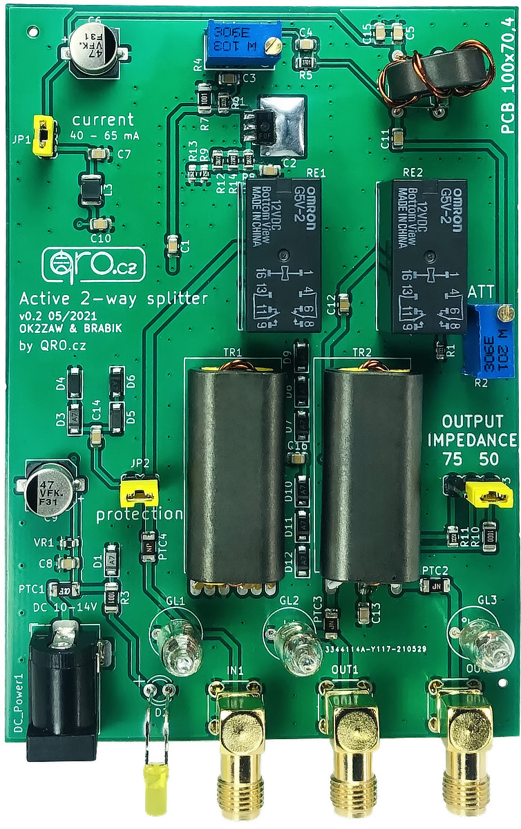
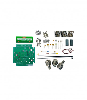
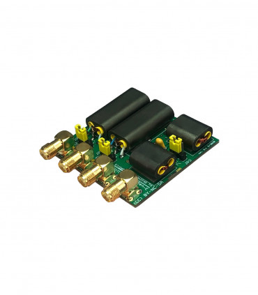
pcb after assembling all the parts
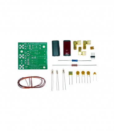
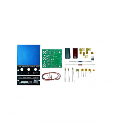
Part list
| NAME | PART | VALUE |
|---|---|---|
| GL 1-3 | neon lamp | lamp 65V AC |
| Q1 | transistor | 2SC5551 |
| L 1-2 | ferrite core | FT50-75 |
| BIAS | trimmer | 10KOhm |
| ATT | trimmer | 200Ohm |
| RE 1-2 | relay | G5V-12 |
| Transformator | binocular | BN-73-6802 |
| D2 | diode | LED diode |
| Wire | wire | 0.45 mm wire |
| IN, OUT 1-2 | connectors | SMA |
| DC power | power jack |
Transformers
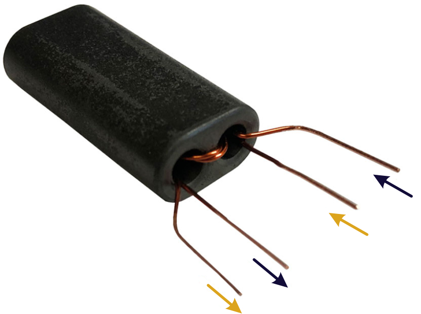
- There are two binocular ferrites
- Both ferrites have got 2 turns - first with bifilar and second with trifilar winding
- Clean coating from the ends. Place wires in right order like on the pictures
- Check it again :)
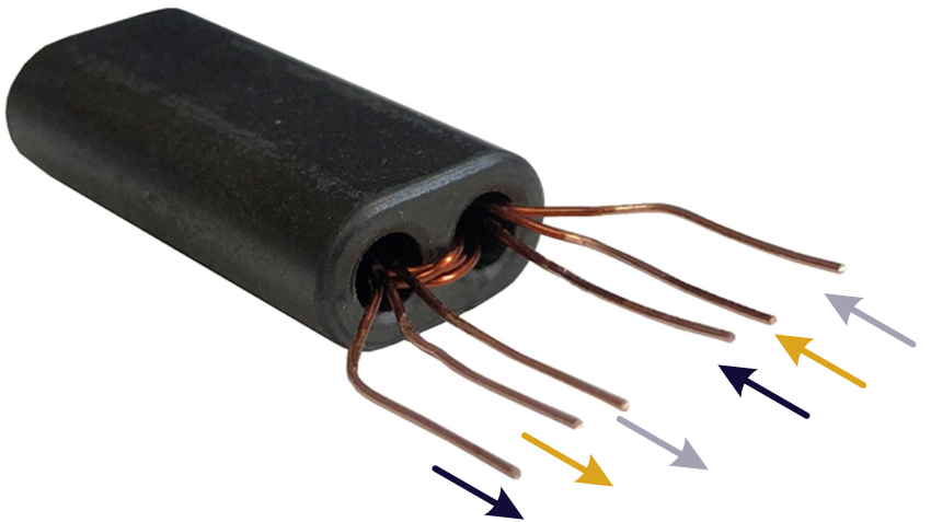
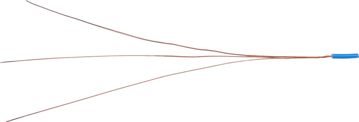
Cut all wires to about 210mm (21cm) - 0.69 feet

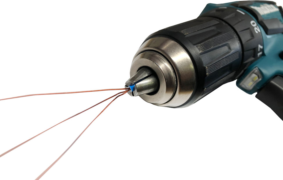
Make bifilar and trifilar wires - you can use small PVC tube and ACU drill
