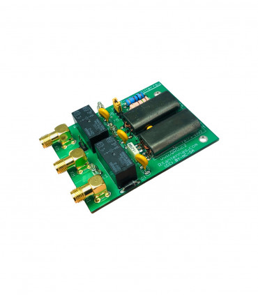
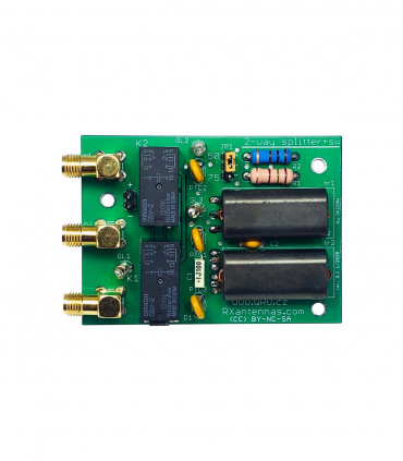
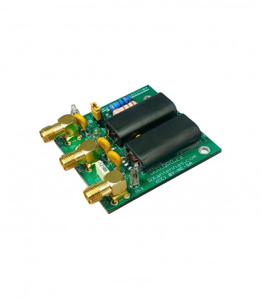
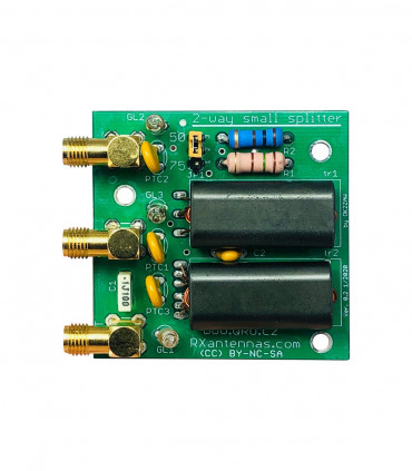
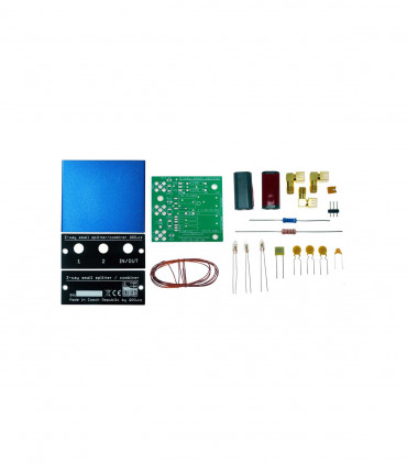
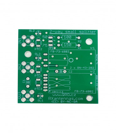
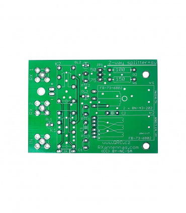
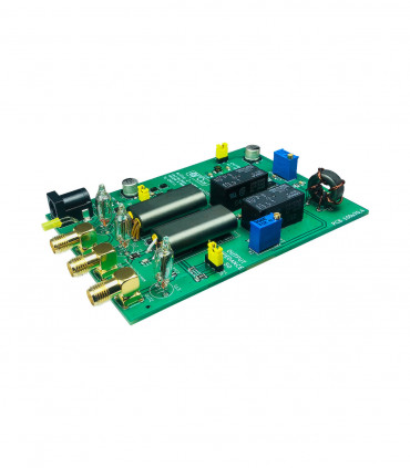
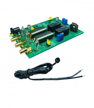
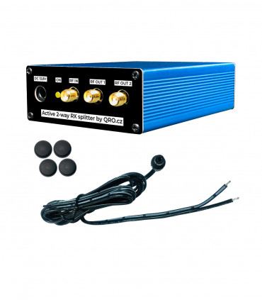
2-way RX small splitter with bypass relay manual
The splitter or combiner is a very useful device. It can provide equal voltages, equal current, or equal power to matched or unmatched loads. Like all passive splitters and combiners, this device is less than ideal. Isolation is maximum only when at least one port are properly terminated. In this case isolation between the two splitted/combinated ports is maximum when the main port is properly terminated.
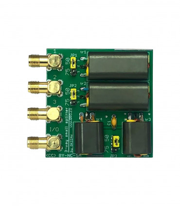
NOTE: This HW is designed only for RX line. There are some more high current and voltage protections on all ports. Both impedances 50 or 75 Ohm can be selected by the jumper.
Jump to
Applications
Splitter
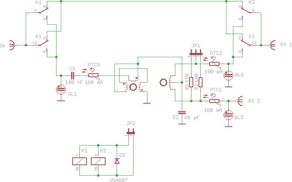
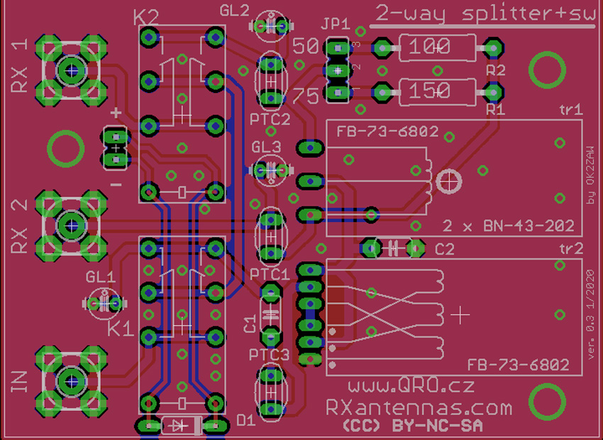
Schematic
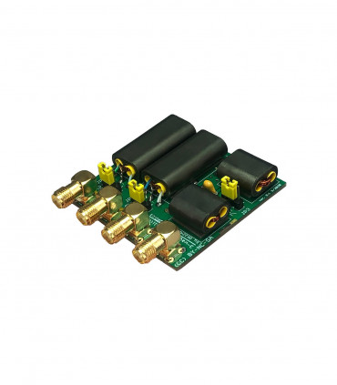
PCB
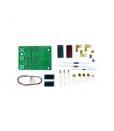
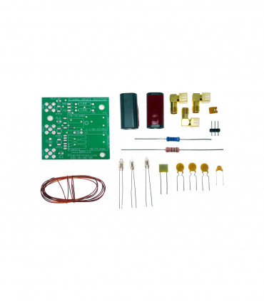
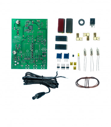
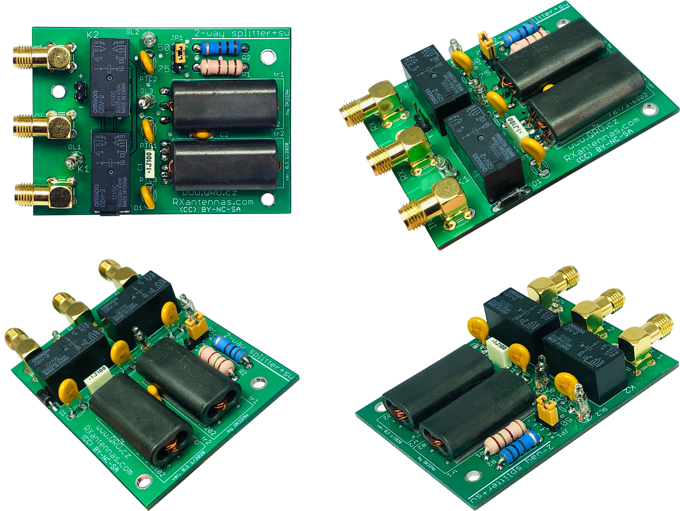
KIT Assembling
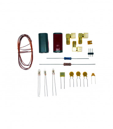
Part list
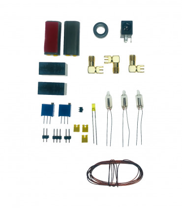
Transformers
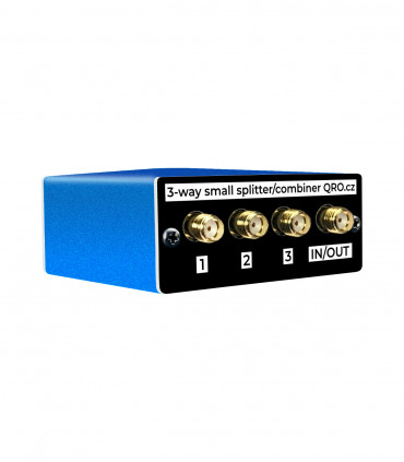
Product details
Applications
Bypass relay
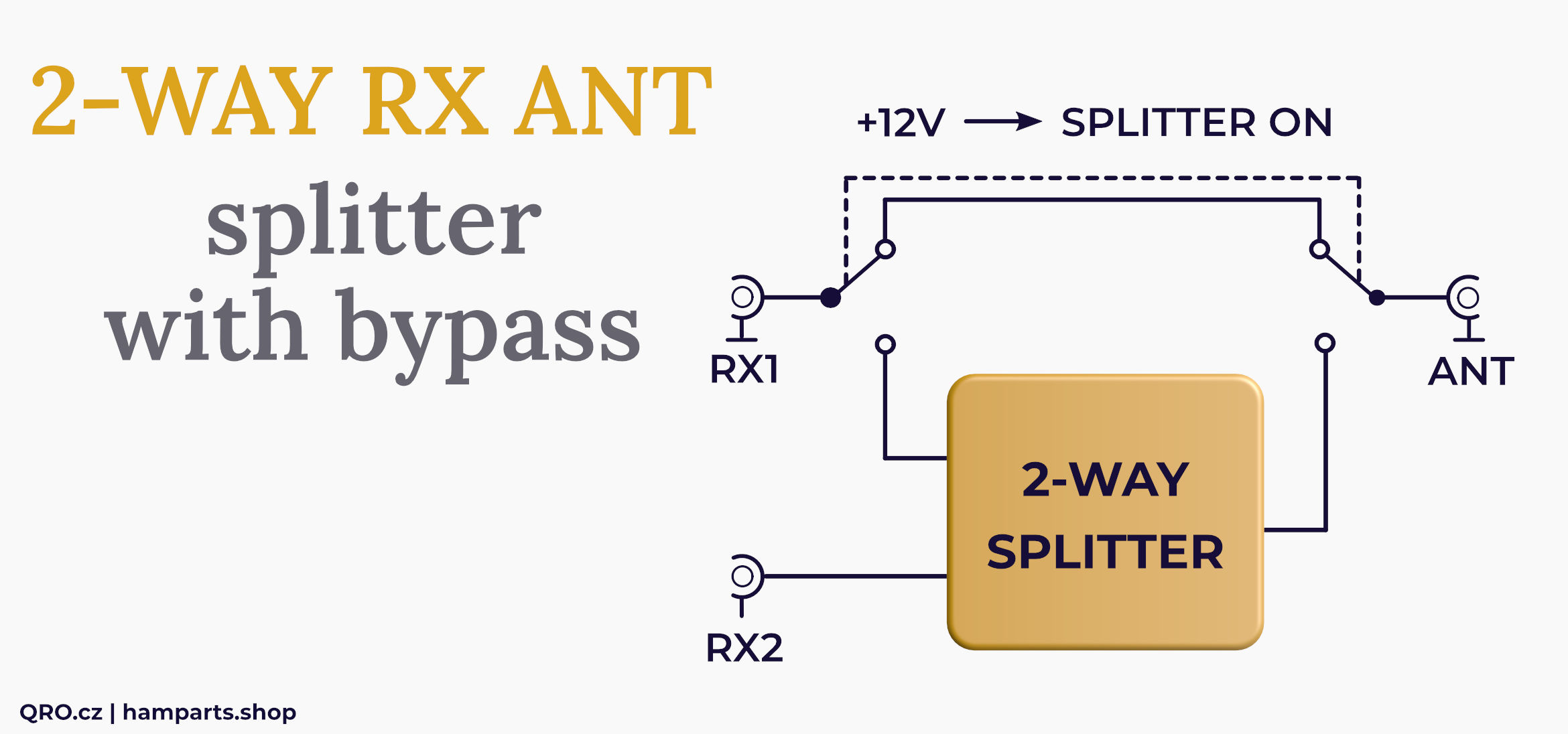
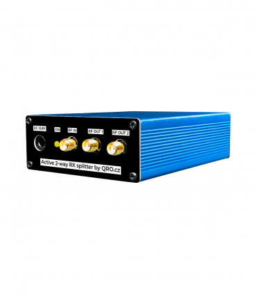
RX antenna splitter for the two RX

RX antenna combiner for 2el Beverage array

RX antenna combiner for 2el end-fire array

Splitter
Schematic
PCB
KIT Assembling
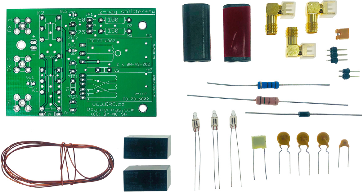
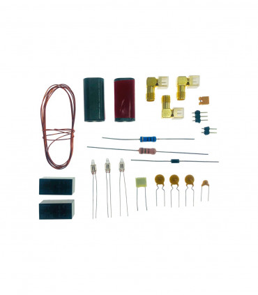
Part list
| NAME |
PART |
VALUE |
| GL |
neon lamp |
lamp 65V AC |
| C1 |
capacitor |
THT 100nF 100V |
| C2 |
capacitor |
THT 68pF 100V |
| D1 |
diode |
1N4007 |
| PTC |
PTC fuse |
THT 100mA |
| R1 |
resistor |
THT 150R / 2W |
| R2 |
resistor |
THT 100R / 2W |
| Transformator |
binocular |
BN-73-6802 |
| SMA |
connectors |
SMA |
| Re |
relay |
G5V2-12 |
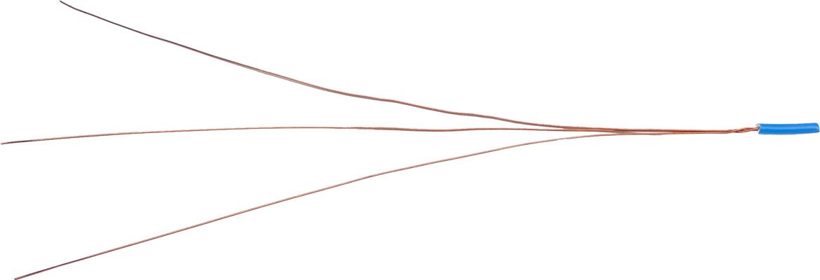
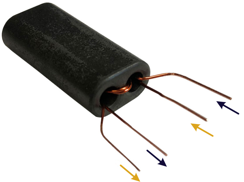
- There are two binocular ferrites
- Both ferrites have got 2 turns - first with bifilar and second with trifilar winding
- Clean coating from the ends. Place wires in right order like on the pictures
- Check it again :)
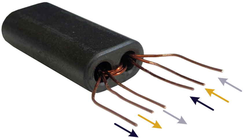
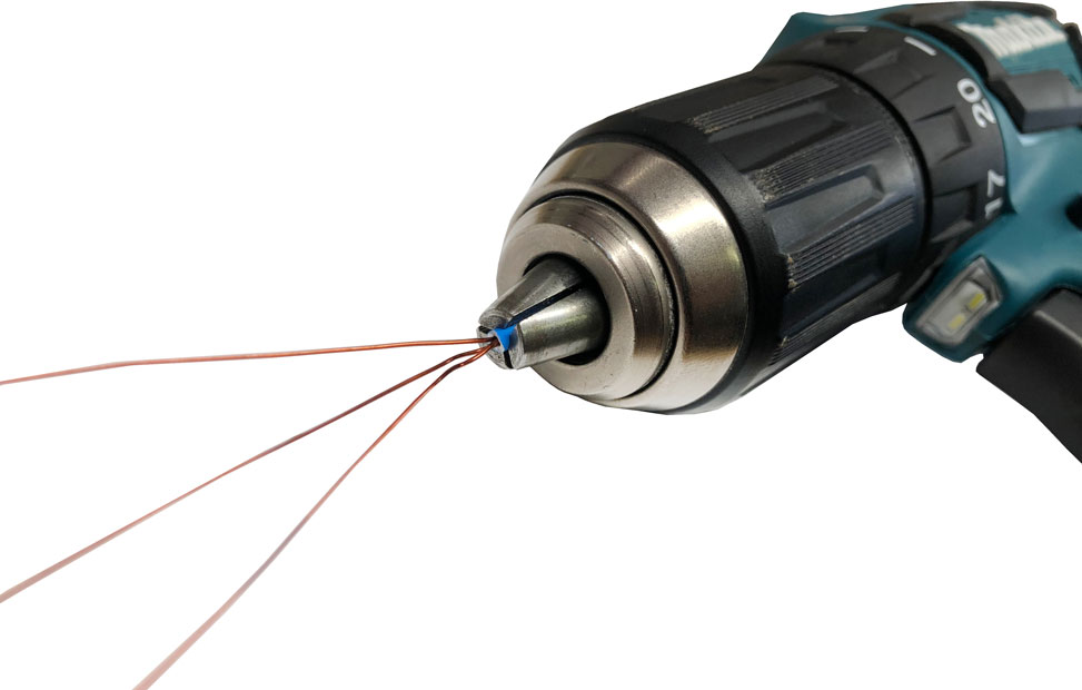
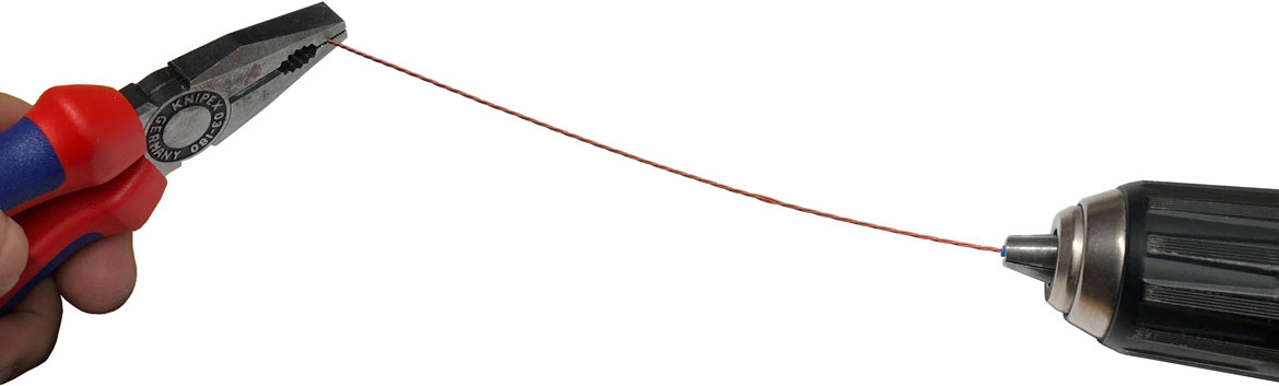
Cut all wires to about 210mm (21cm) - 0.69 feet
Make bifilar and trifilar wires - you can use small PVC tube and ACU drill