REMOTIUS 64 manual
This is manual page for REMOTIUS 64 - universal remote controller with 53 outputs. You can directly connect K9AY++ or 7ANT as well as your custom projects.
Jump to
Front panel description
Rear panel description
Parameters
Connection and connectors description
Analog input
Jumper settings
Remote control
UI examples
QUICK setup
Product details
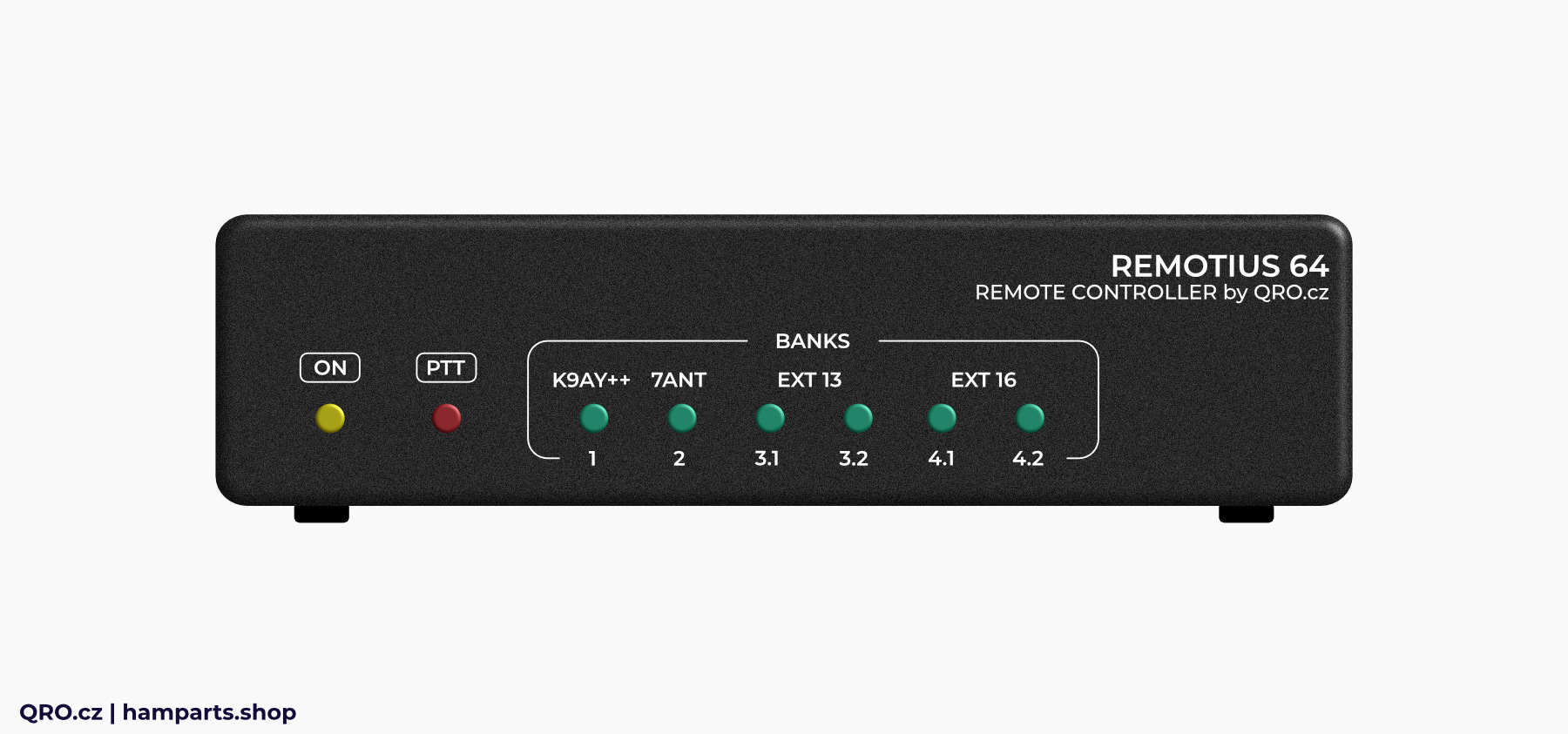
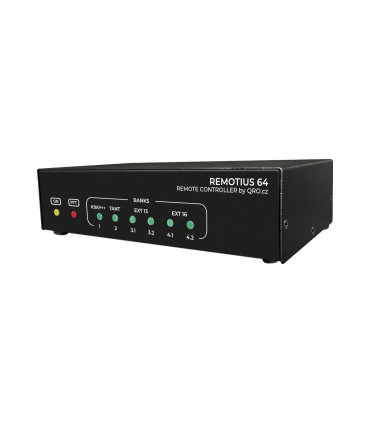
Front panel description
1. LED - Status LED
- LED - status LED
- PTT - PTT information
- ON - controller is ON
- BANKs - status of every output bank
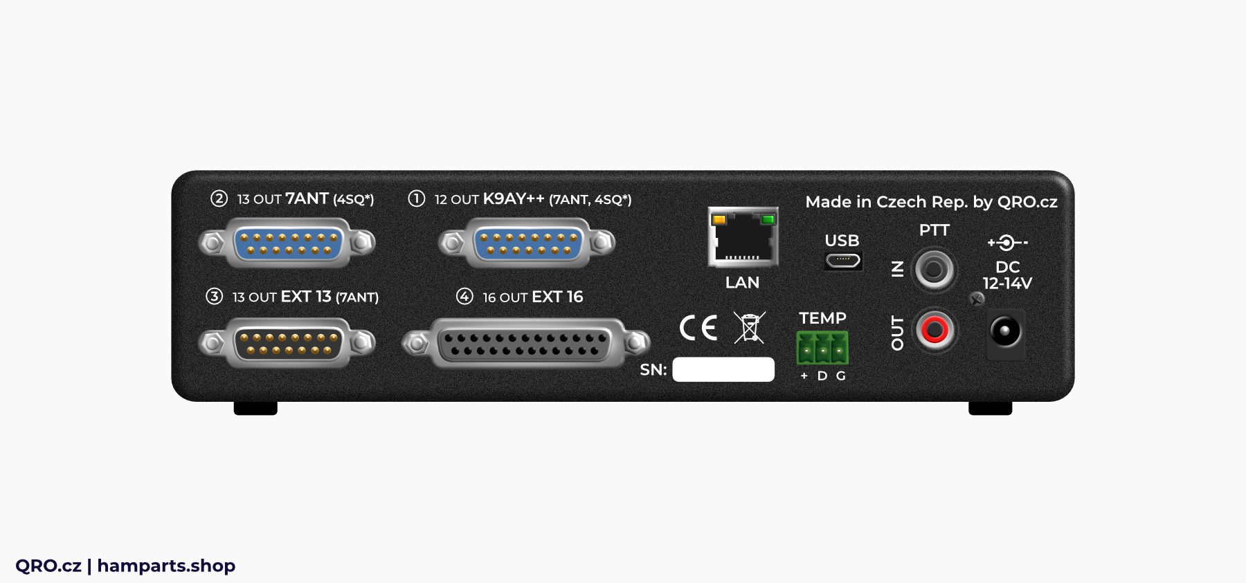
Rear panel description
1. DC
- input DC 12 ~ 14 V
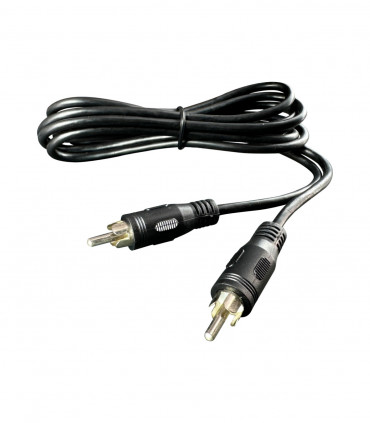
2. PTT RCA
- PTT IN and OUT
3. LAN
- 10/100 MBit LAN with DHCP
4. USB
- USB port for FW upload
5. TEMP
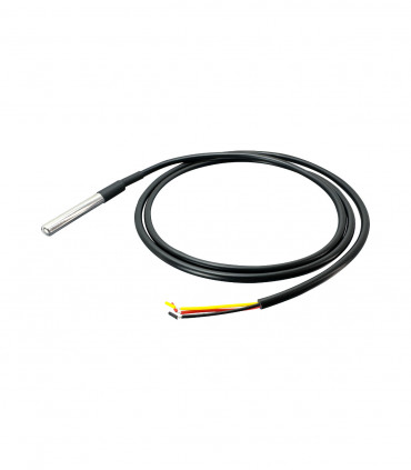
- port for 18B20 temp sensors
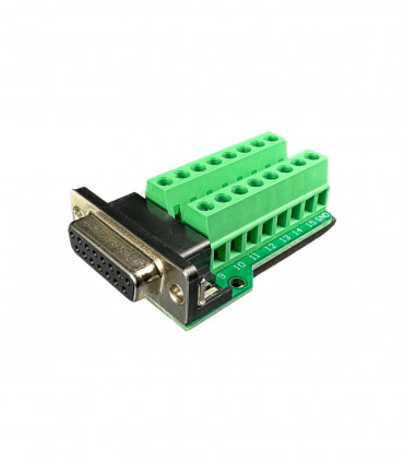
6. BANK 1 ~ BANK 3
- DB15 male
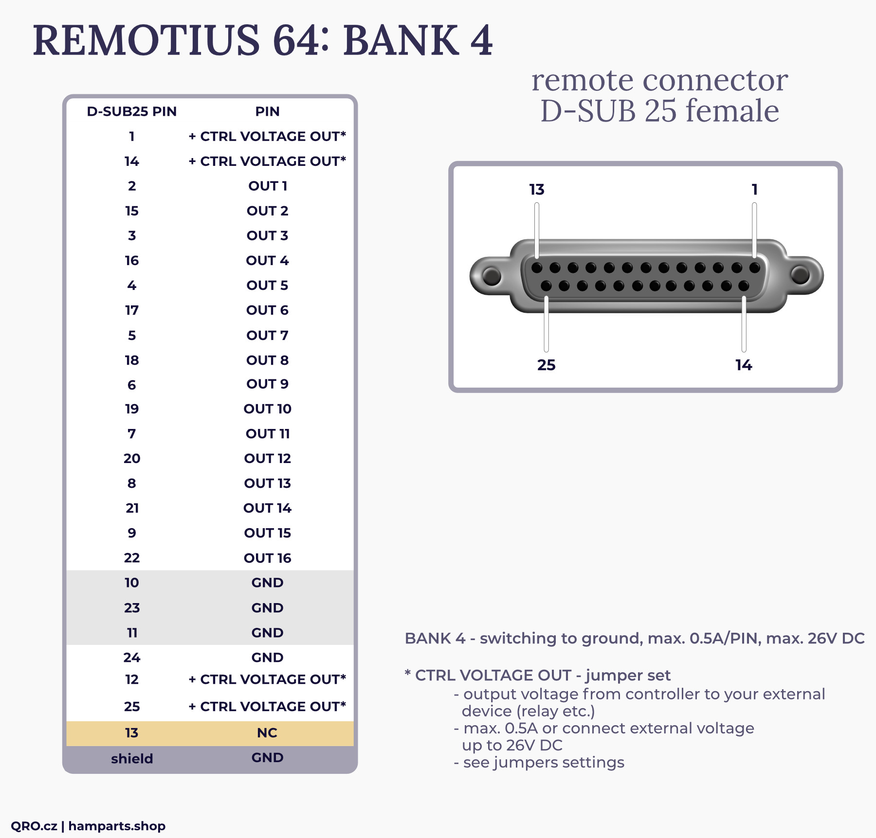
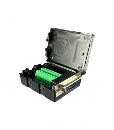
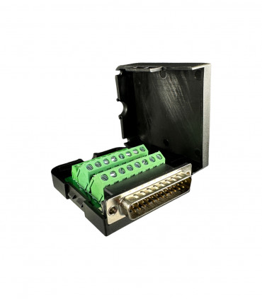
7. BANK 4
- DB25 female
See connector description section
Parameters
- Universal 53 outputs with + voltage or GND outputs (depends on bank) - image
- Controller supply voltage 12 ~ 14 V, max. 16 V DC/1.5 A, DC plug cable
- BANK 1 to 3 have positive drivers max. 26V DC
- BANK 4 is switching to ground
- JUMPERS for different configuration (see manual)
- BANK 1 and 2 need EXT power supply max. 26 V DC
- BANK 3 internal or EXT power supply controller voltage or EXT max. 26 V DC
- BANK 4 could have 12 V output for external devices (relays), max. 0.5 A
- BANK output current max. 500 mA per output, 700 mA total per bank
- Voltage drop for positive driver typ. 0.2 V for +12 V input and 0.7 V including fuse
- Output voltage for positive driver is input voltage minus abt 0.7 V
- BANK 4 voltage drop typ. 0.8 V for +12 V
- LED indication: ON, BANK and PTT
- Temperature sensor up to 10 of 18B20
- PTT IN: RCA or BANK 1 or 2
- PTT HOT switch protection for ALL Banks
- PTT OUT: FET 0.5 A, 50 V DC (no delay)
- Analog input max. 16 V DC
- LAN 10/100 MBit with filter and protection
- ONLY DHCP IP address - not static
BANKs summary
- BANK 1 - positive output needs external DC supply (max. 26 V, 0.7 A)
- BANK 2 - positive output needs external DC supply (max. 26 V, 0.7 A)
- BANK 3 - positive output supply from controller or Vext (pin 15), (max.26 V, 0.7 A)
- BANK 4 - negative output switching to ground (max. 50 V, 0.5 A per pin)
- BANK 4 - possible DC out for ext. device Controller supply voltage, max. 0.5 A
Analog input
- One analog input for 4SQ UI
- Simply indication - low accuracy ADC
- Possible to use BANK 1 or 2 (shared one ADC)
- Internal 30 turn trimmer for full scale set
- Full scale Voltage: min. typ. 4.2 V, max. 16 V DC
- Overdrive protection
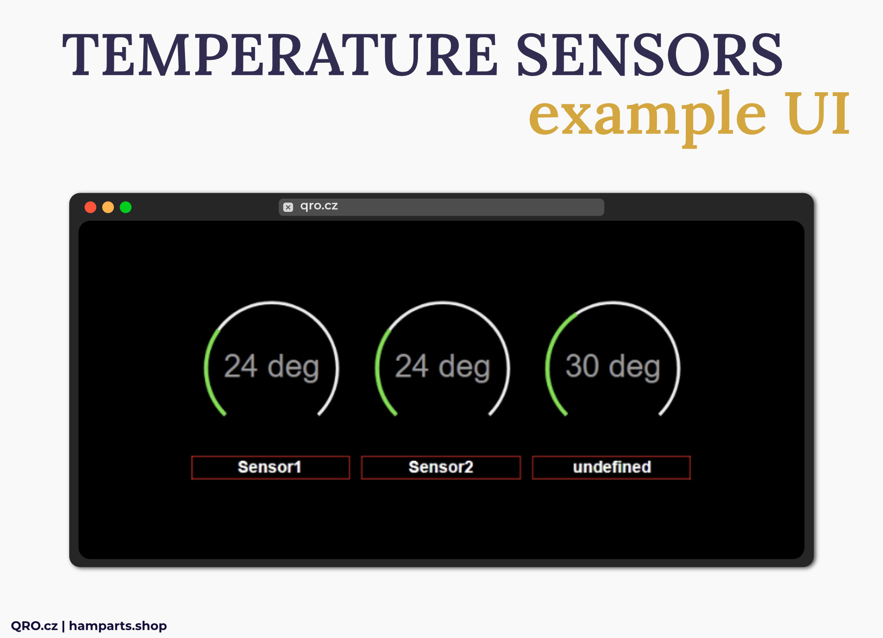
Temperature sensor
- Optional input designed for 18B20 sensors
- Star topology connection for more senseors
- You can use up to 10 pieces
- Sensor voltage 3V3
- Simply RFI filter
Connection and connectors description
There are four different output banks. Each bank could have own User Interfacei (UI) control - also multi users could control it.
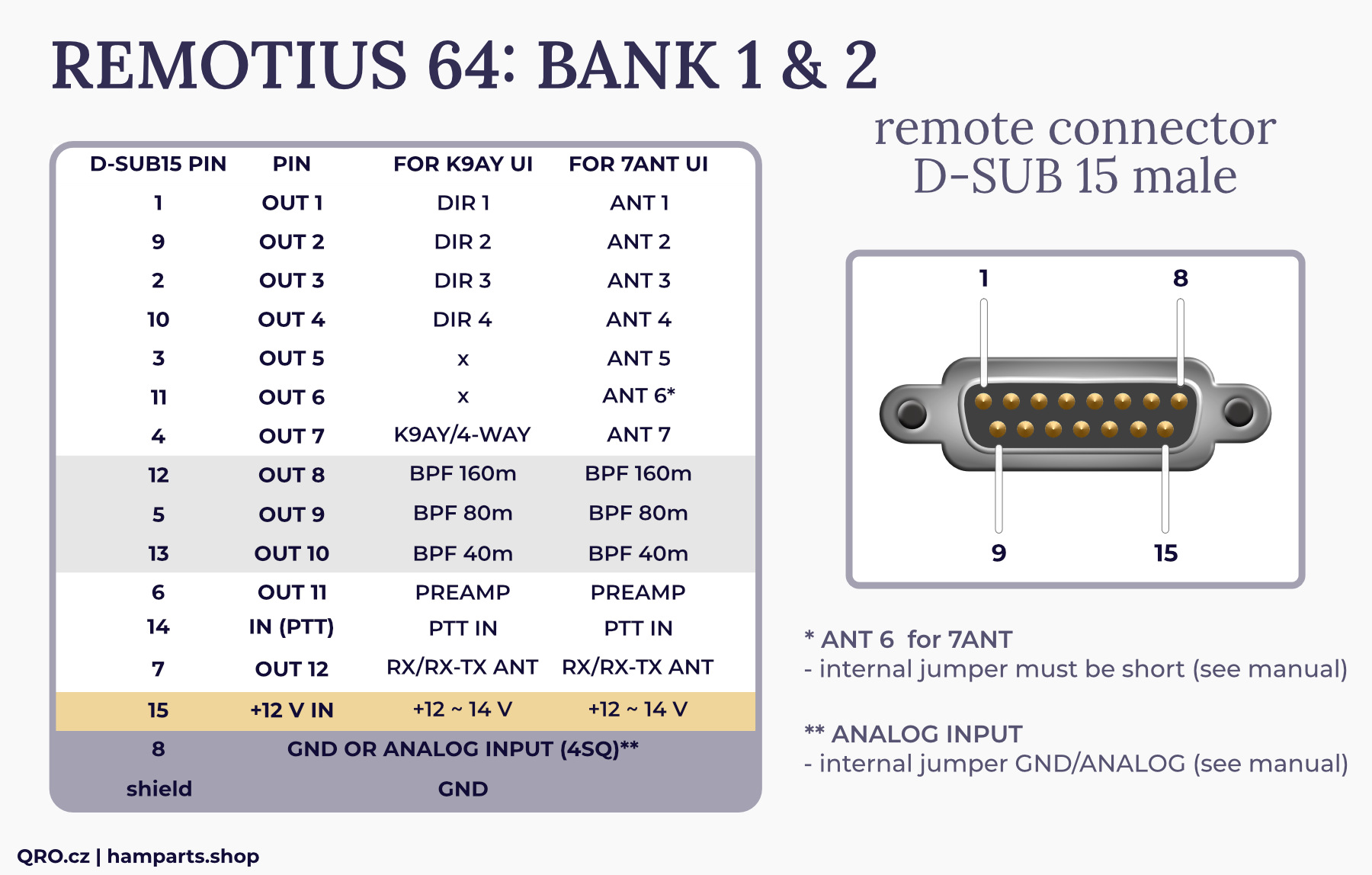
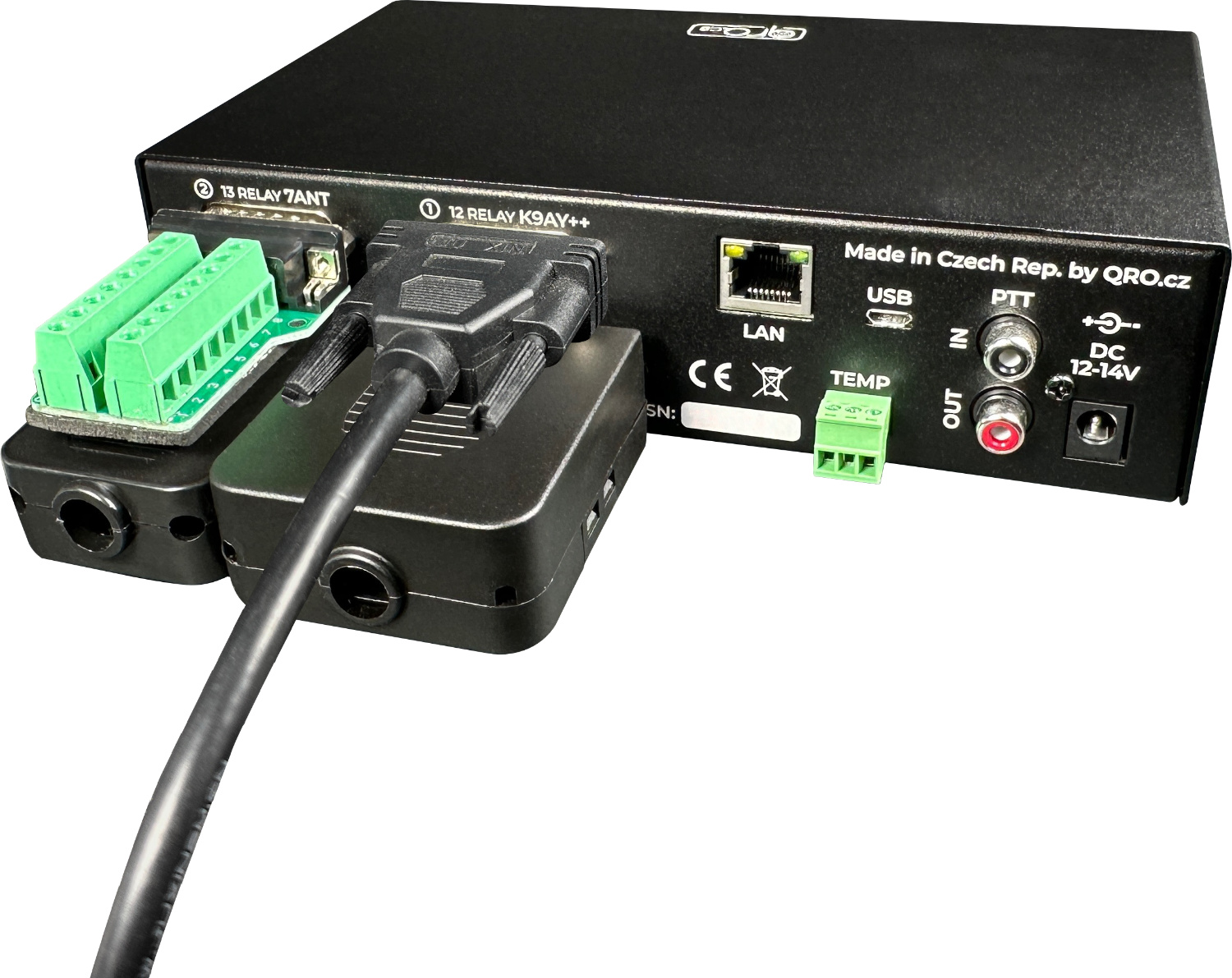
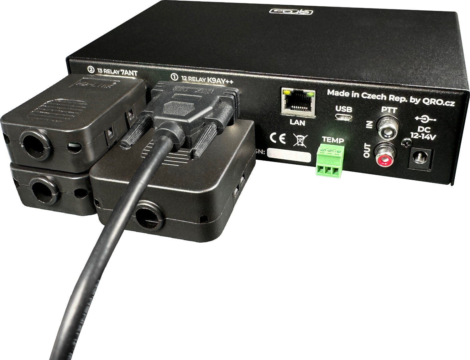
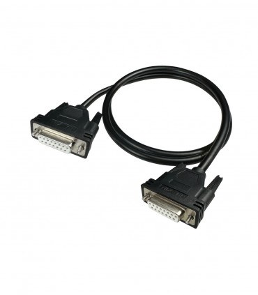
Some banks (1 and 2) are directly compatible with our RF controllers - K9AY++/4-WAY and 7ANT. You can directly connect these DB15 outputs to RF controller RC inputs. Cable must be 1:1, you can buy D-SUB 15pin cable.
Bank 3 could be used as universal 13 outputs but also for K9AY++ or 7ANT. In this case use ONLY UI for this controllers, not 13 OUT one. All 13 outputs could be used as single pins ON/OFF or grouped into switch 1 of X.
Bank 4 is 16 outputs - could be used as single pins ON/OFF or grouped into switch 1 of X.
With our connectors description you can connect any of your hardware. Banks 1 to 3 have got positive outputs (output is + voltage), Bank 4 has got negative drivers - active pin is switched to ground. Bank 4 could have a DC out pin configured by jumpers, where can be the DC voltage from the controller out to your external device (switching relays) - maximal output current is 0.5A.
There is one common PTT in controller. PTT input could be on RCA (PTT IN) of from Bank 1 or 2 (see jumpers settings). PTT OUT is no-delay output from PTT IN (ANY). There is FET switch max. 50V DC, 0.5A.
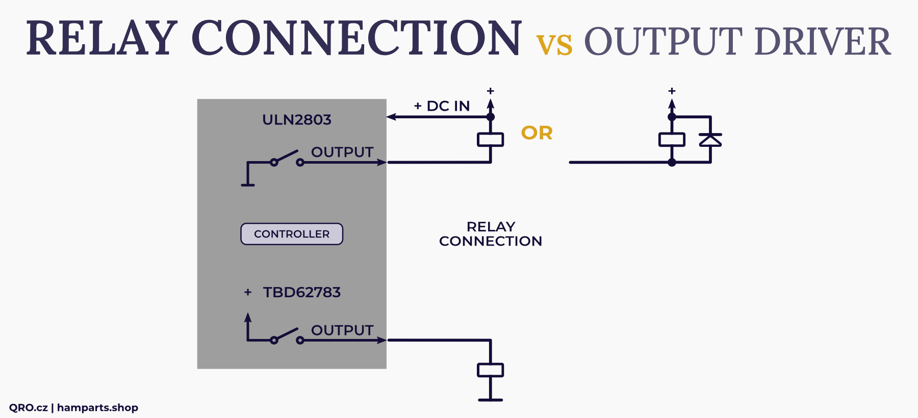
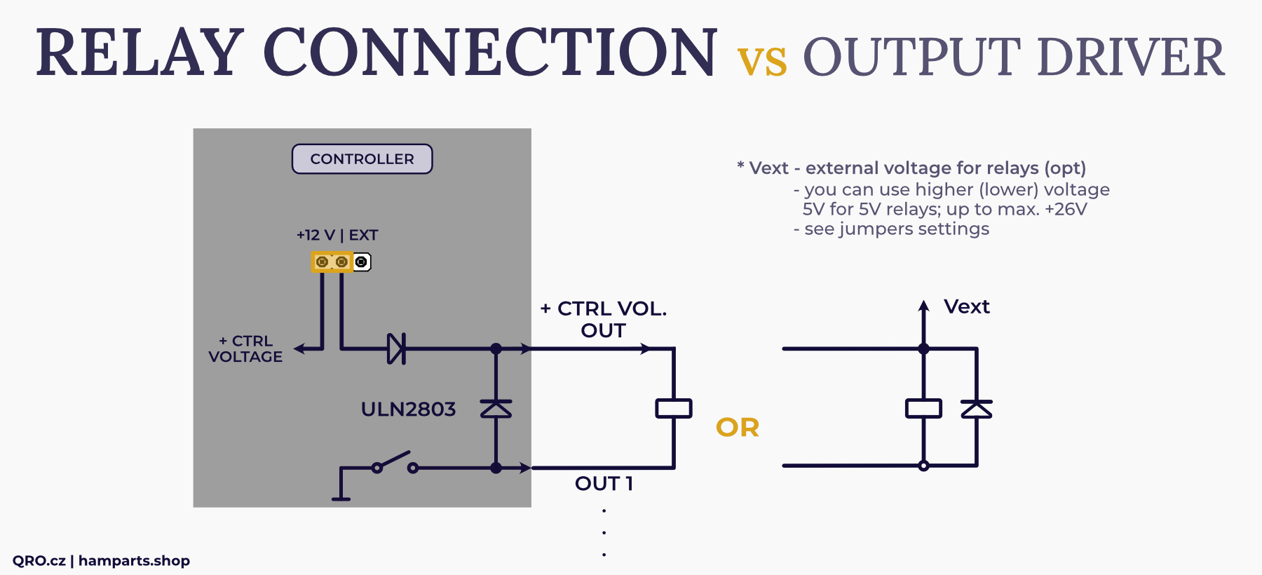
Difference between Positive (TBD) and Negative (ULN) outputs
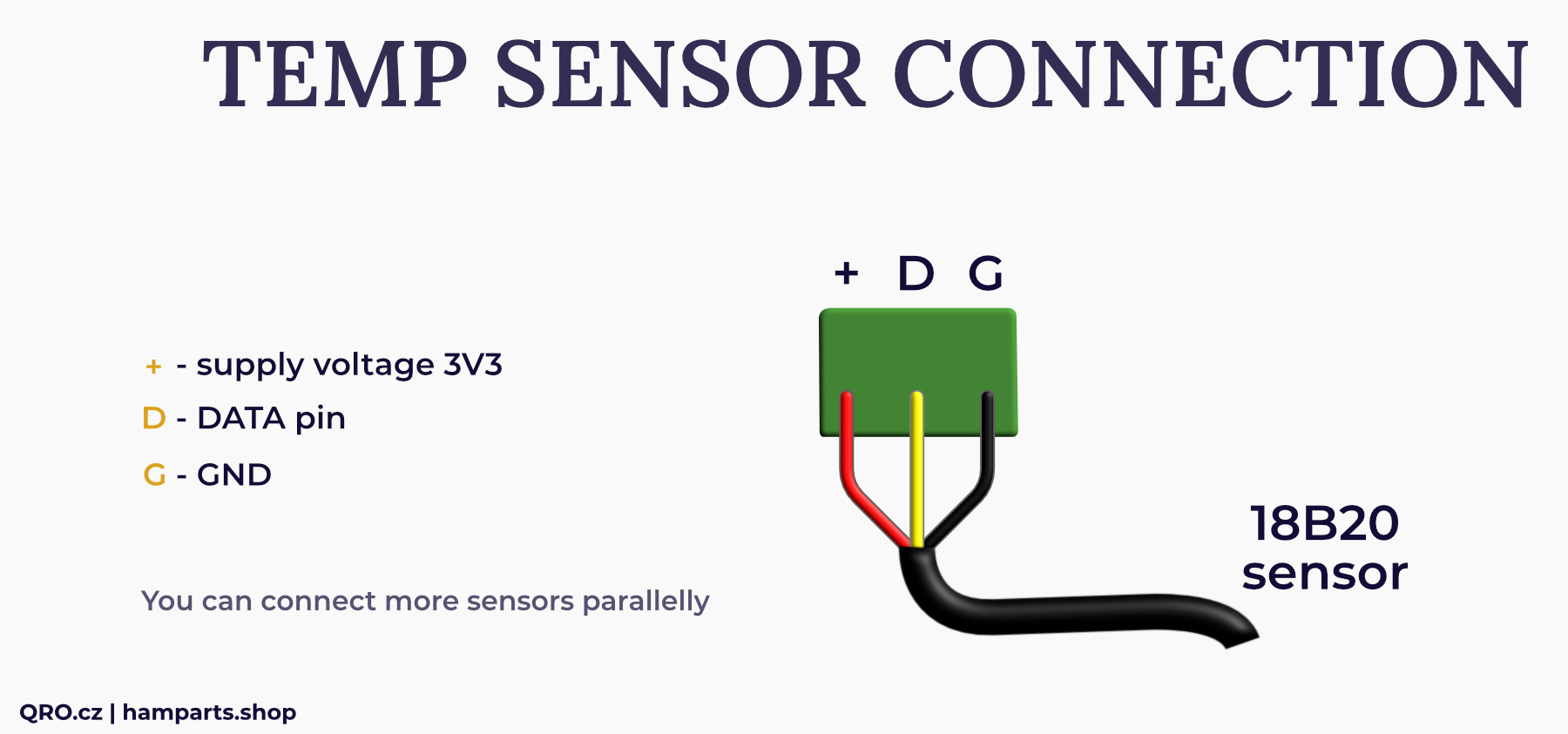
TEMP connector
- +/- - DC voltage 3.3V
- D - data pin
- G - GND
PTT RCA connector
- PTT IN - is activated by connecting to ground (transmitting)
- PTT OUT - is output from PTT IN with no delay. Output is FET with maximal 50V DC and 0.5A
BANK 1, BANK 2: D-SUB 15 male
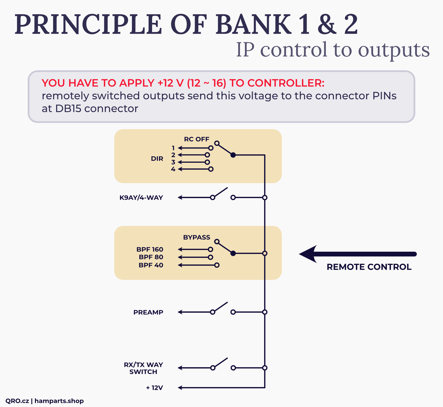
BANK 1 and 2 are directly designed for our controllers (K9AY++ and 7ANT) but is could be used as universal 12 outputs or you can follow out configuration for antenna, BPF and preamp switching.
There is principle of BANK 1 and 2. The switches are virtual, made in UI and this is an example how it works. In the case of 7ANT UI, the first group switch has got 7 positions (OUT 1 to 7). These Banks (1 and 2) need external supply voltage - maximal is 26V DC, current 0.5A per pin and 0.7A total per bank. Please, see also Jumper settings section for configuration examples.
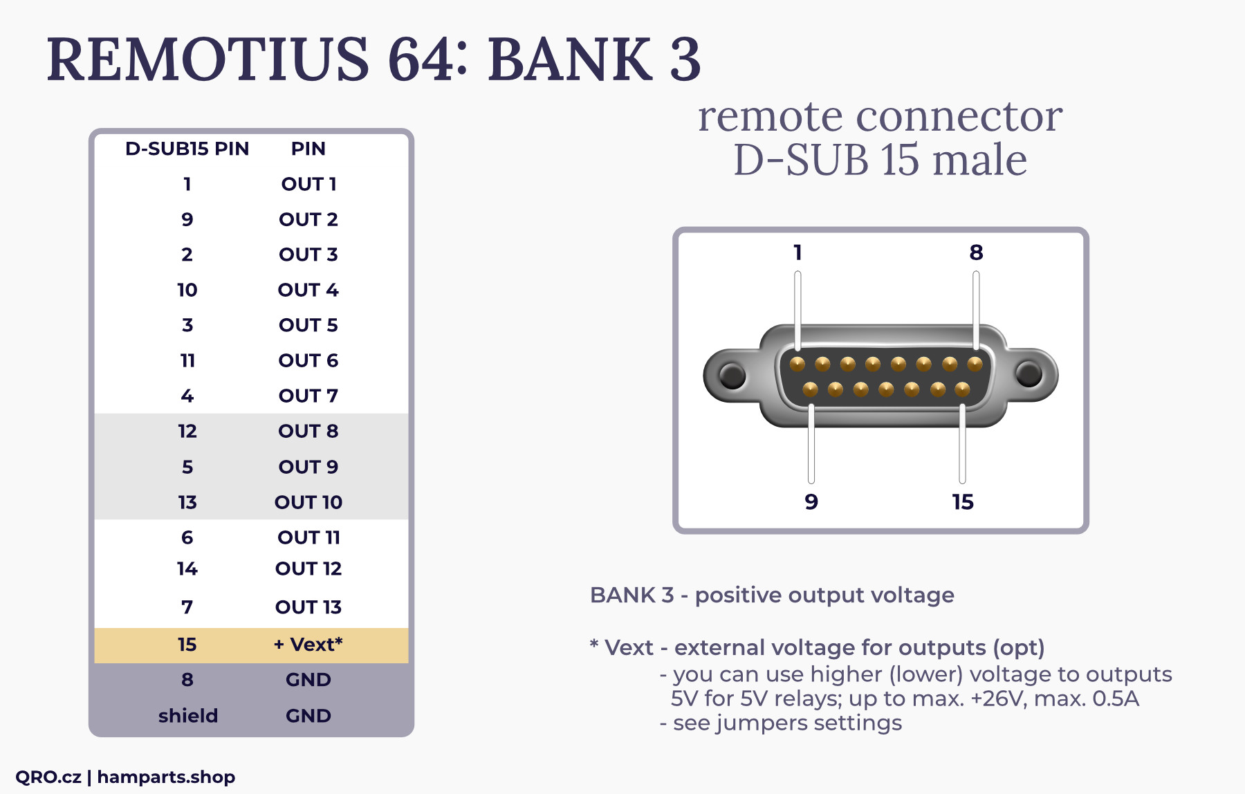
BANK 3: D-SUB 15 male
There is 13 universal outputs with positive drivers inside - activated pin has got + voltage at output.
This Bank 3 can use controller supply voltage or external one - maximal is 26V DC, current 0.5A per pin and 0.7A total per bank.
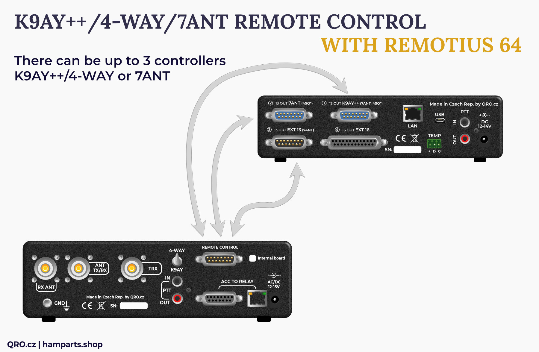
Direct compatibility
You can connect up to 3 pieces of 7ANT controller. This allows you to have full 7ANT 3 OUT RX antenna switch remotely controlled. Each radio could have own User Interface and be independent. You are able to combine classic UI and Beam Map one.
BANK 4: D-SUB 25 female
There is 16 universal outputs with negative driver - active pin is switched to ground. You can use outputs as a single pin or could be grouped to switch 1 of X - this is made in the User Interface configuration.
+ CTRL VOLTAGE OUT
- could be set by the jumper (see jumper settings) as an output - controller supply voltage could be used for external device (relays) - maximal 0.5A, or as an input - protection diodes in driver will be used
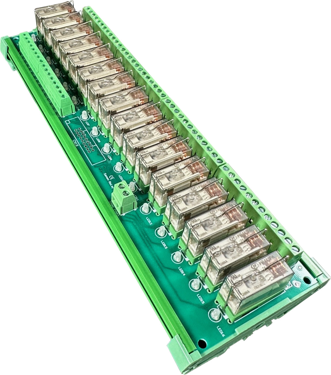
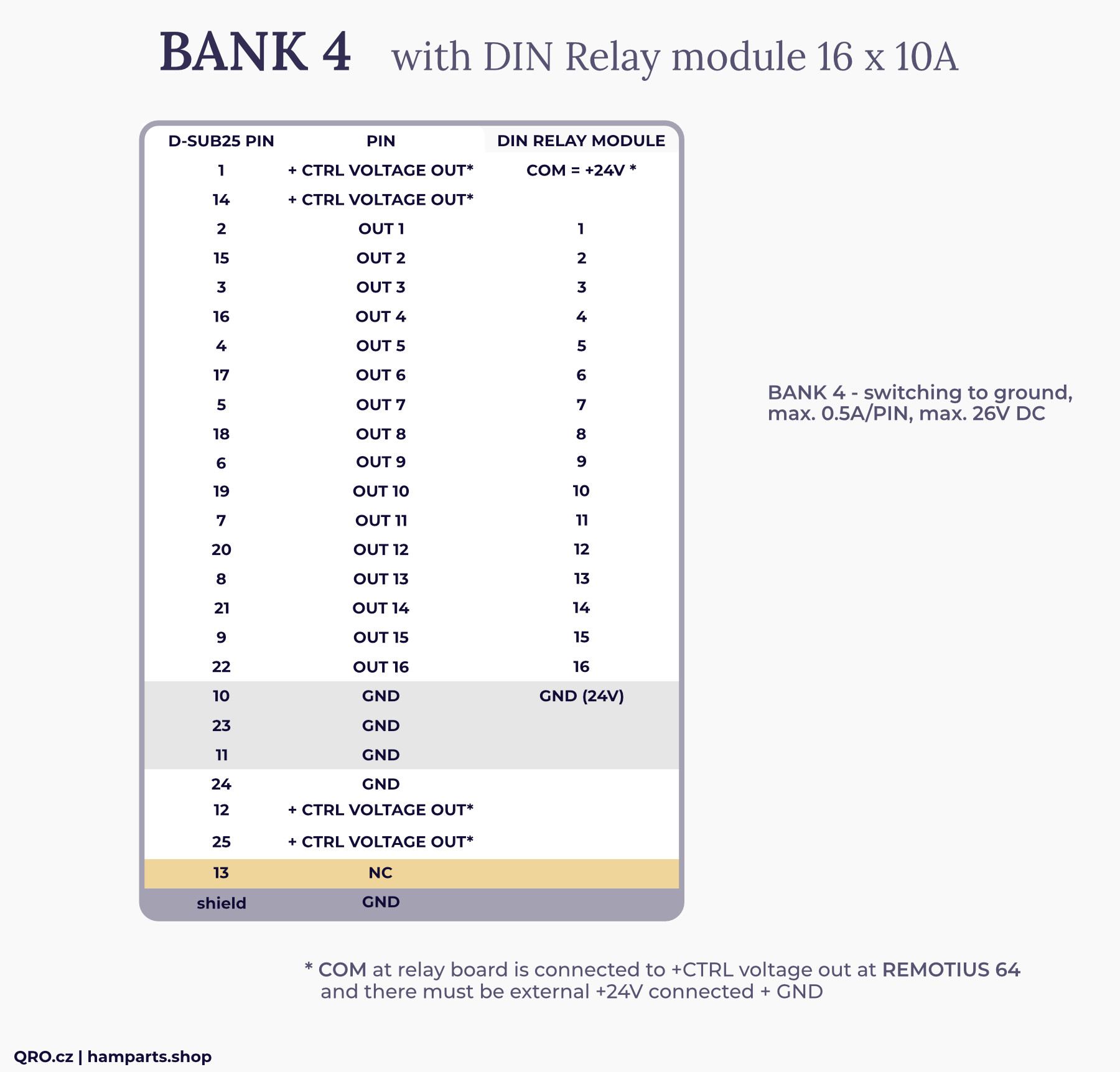
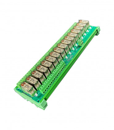
BANK 4: with DIN Relay module 16 x 10A
This is an example of connecting a relay board to the Remotius 64. In case of BANK 4 it is switched by ULN drivers to ground. This example is for our 24V relay board. It is necessary to connect an external 24V DC power supply. If all relays are switched, the current will be about 0.4A.
DC JACK
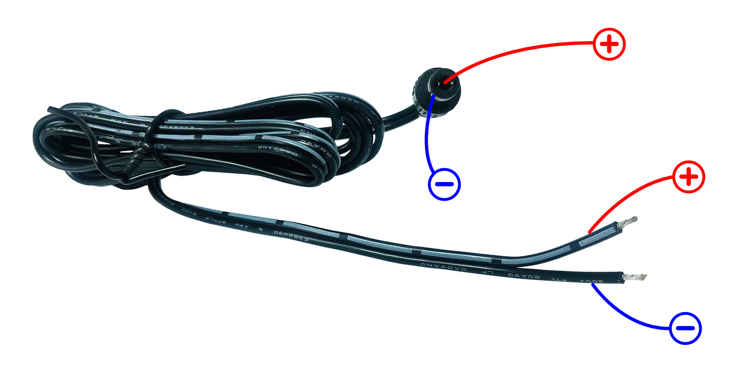
Supply voltage connector. Supply voltage is 12 to 14 V DC (max. 16V) and max. 1.5A
Analog input
There is one Analog input. Could be used for simply indication of the dummy load power in 4SQ, 2EL array etc.
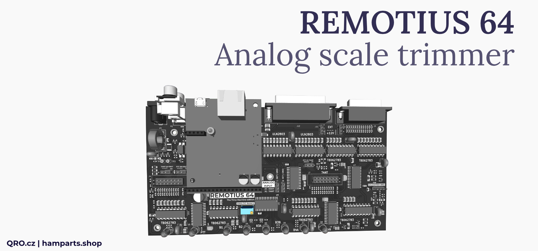
This Analog input could be set to BANK 1 or BANK 2. PIN 8 at DB-15 connector could be set by Jumper to GND or Analog IN. Please see Jumper settings.
Analog input has got a 30 turn resistor trimmer (R74 ANALOG RANGE), you can set full range for input voltage. Minimal voltage for full range is around 4.2 V DC, maximal is 16 V DC. There is protection inside.
Jumper settings
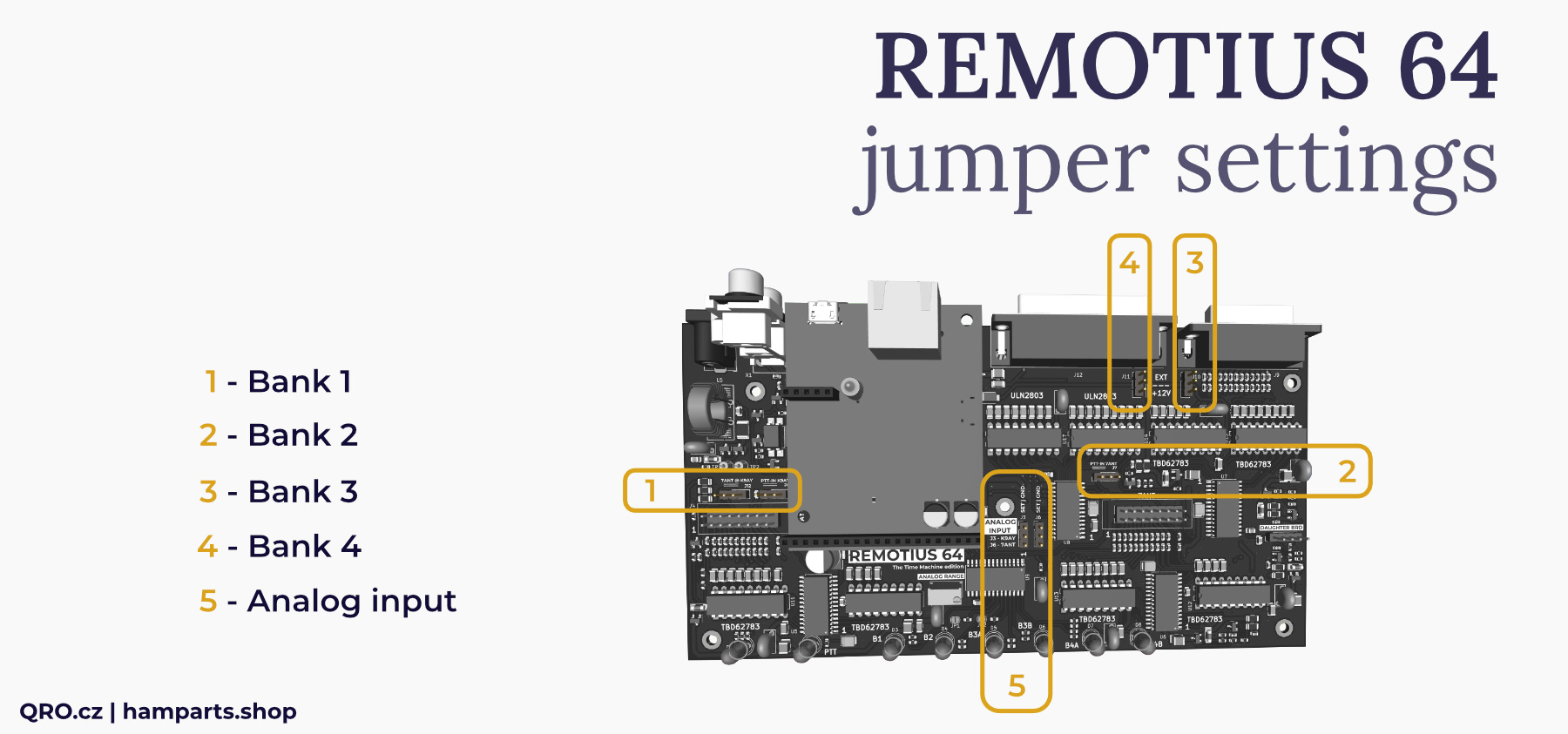
There are some Jumpers on the board. These jumpers offer different configuration options for the output banks, Please, have a look at the pictures and check all possibilities.
⚠ When you do any changes - please, switch controller OFF and disconnect power supply.
⚠ You can open the enclosure without losing the warranty.
1. BANK 1
- J12 - selecting between K9AY and 7ANT controller. Position 7ANT enables OUT 6
- J4 - PTT IN from connected controller to Remotius 64 - this PTT IN will lock all Banks!
2. BANK 2
- J7 - PTT IN from connected controller to Remotius 64 - this PTT IN will lock all Banks!
3. BANK 3
- J10 - voltage for the output driver
Position +12V = output pins will be supplied by the voltage from Remotius 64
Position EXT = output pins will be supplied by EXTernal voltage (PIN 15)
* See more in Bank and connector description
4. BANK 4
- J11 - output voltage from Remotius 64 to external device or EXT
Position +12V = PIN 1, 14, 12, 25 (+ CTRL VOLTAGE OUT) will have supply voltage from controller
Position EXT = external device has got own supply voltage, connecting to Remotius 64 helps to protect output drivers by internal diodes
* See more in Bank and connector description
5. ANALOG INPUTS
There is one shared analog input to CPU. You can use it for simply information about RF power in dummy load of 4SQ
- J3 = BANK 1
- J6 = BANK 2
When you select one of the jumper to SET then PIN 8 at D-SUB connector works as Analog input
! Ground is then only at D-SUB shield!
GND position of jumper = PIN 8 is a GND
SET position of jumper = PIN 8 is Analog IN
Remote Control
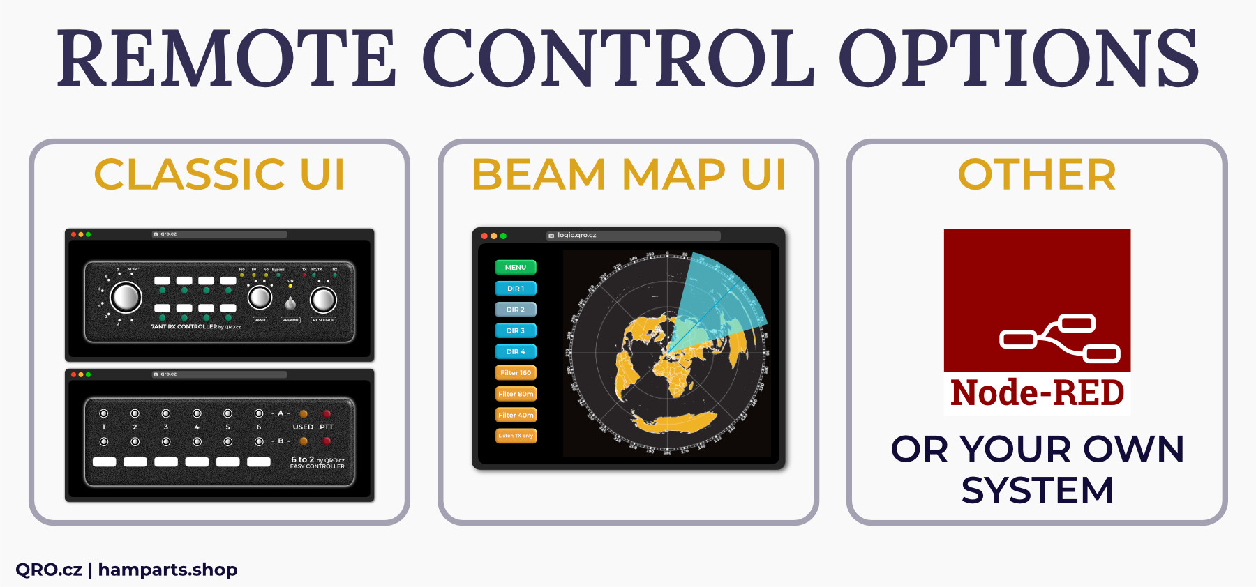
Remotius 64 could be controlled by the three basic ways. If you want to know more about REMOTE SYSTEM, please read our technical articles.
1. CLASSIC User Interface (UI)
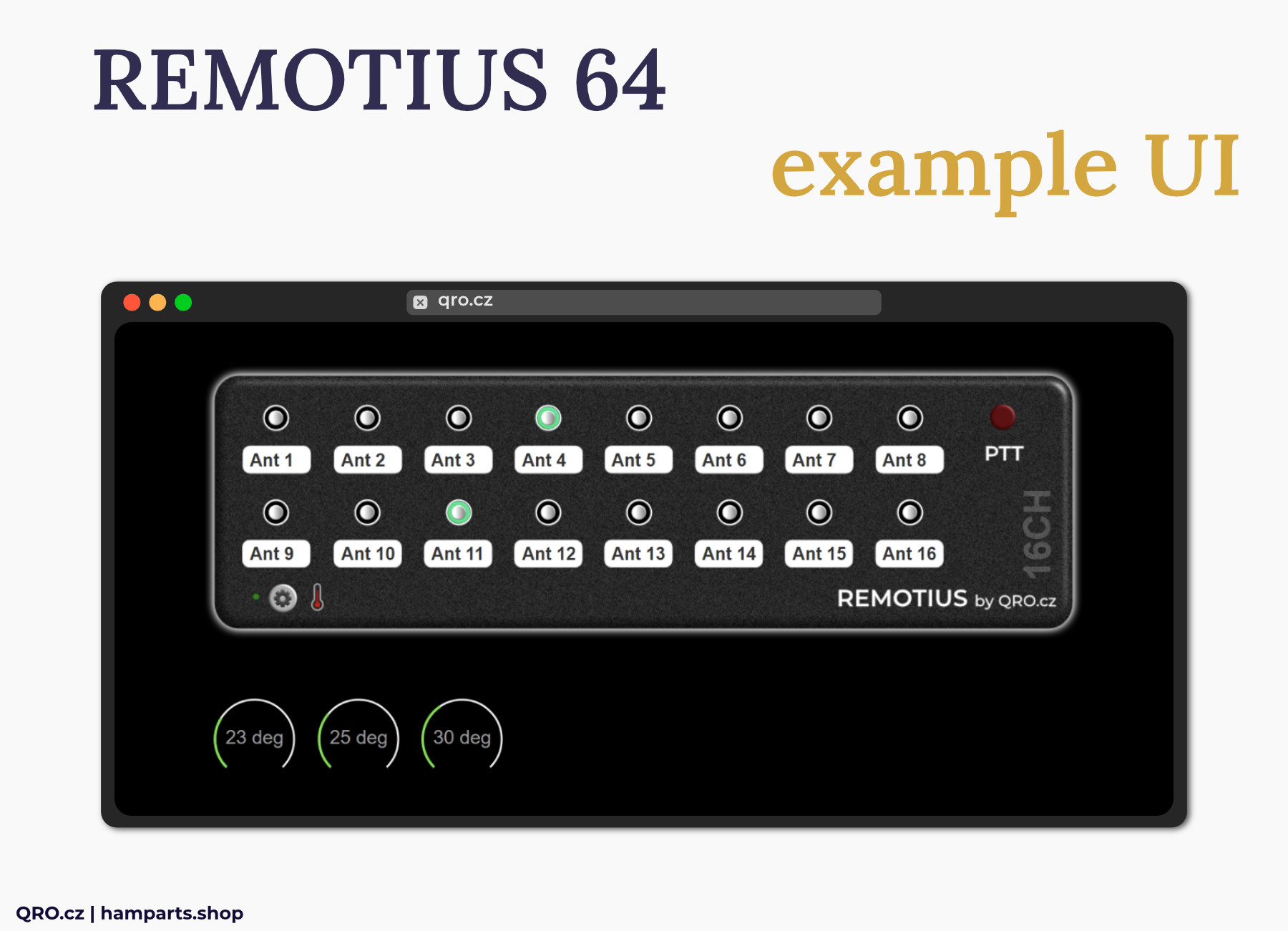
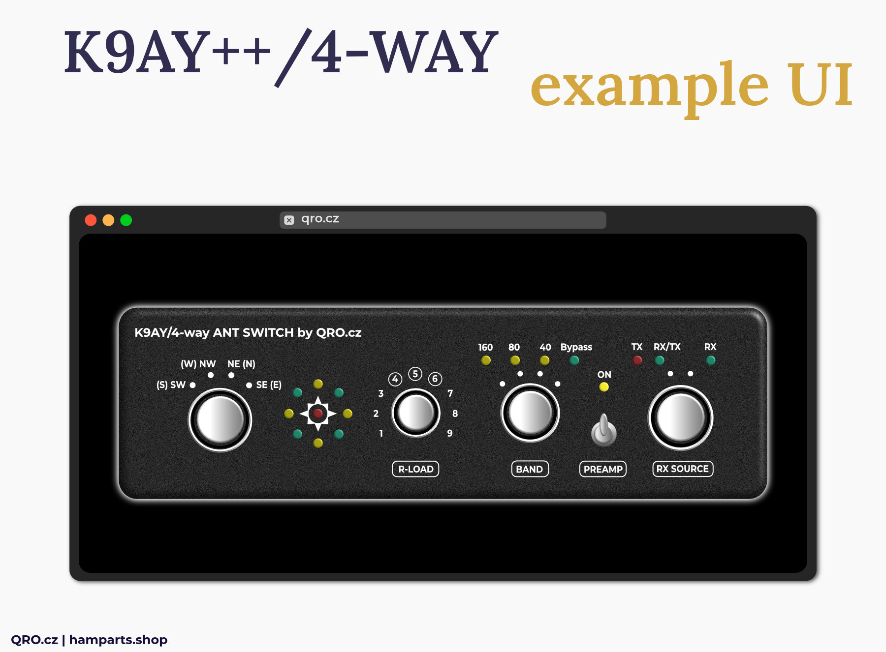
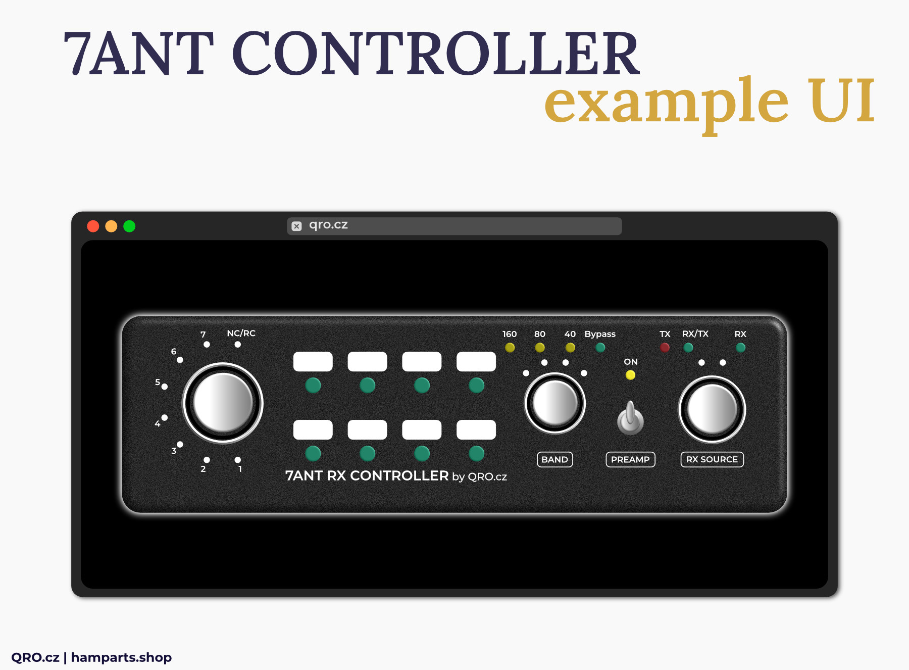
- There are UI with the similar look as the HW controllers. You can use this web page UI to control outputs by clicking on buttons, you can change labels, colour, font size etc.
2. BEAM MAP UI
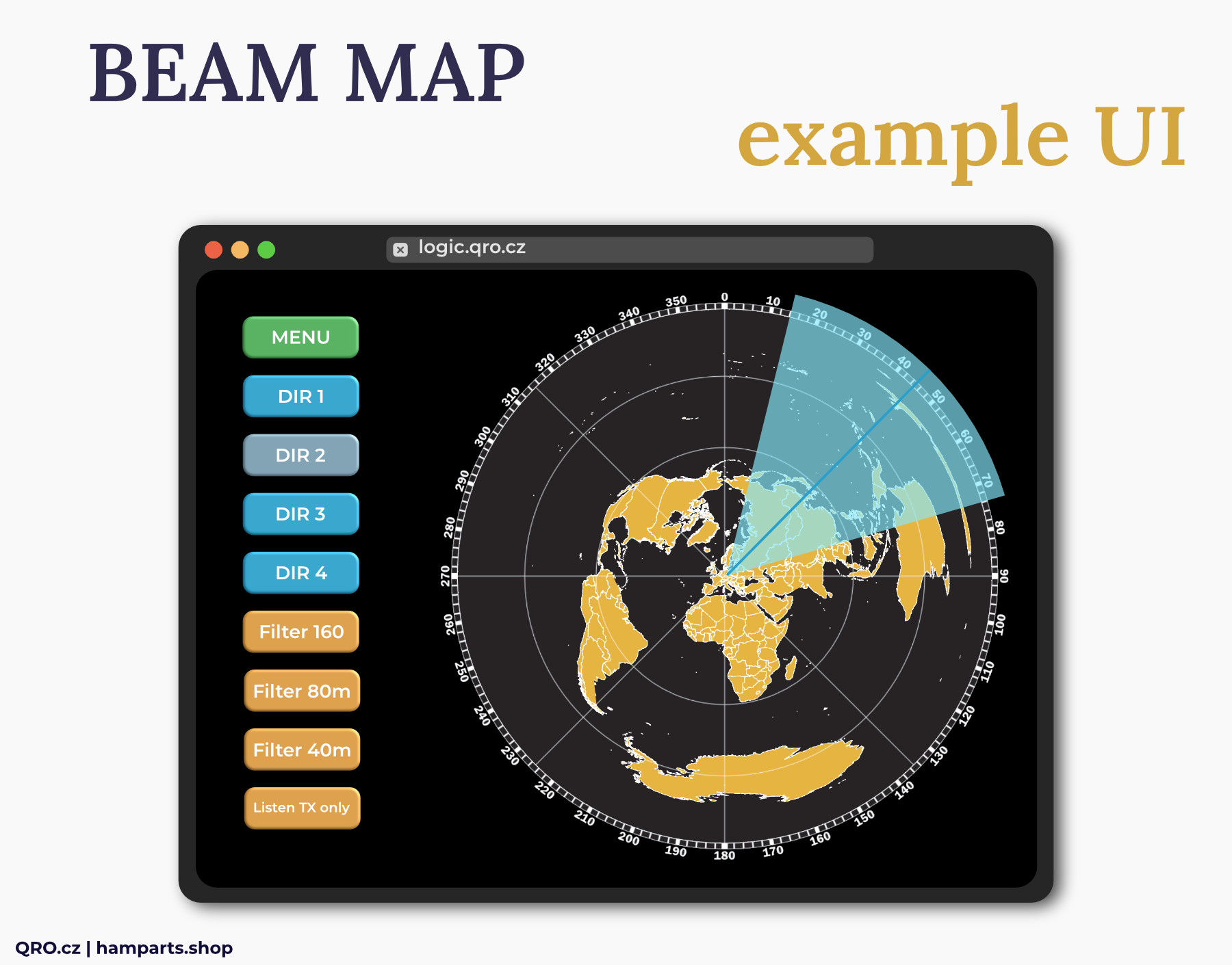
- This is UI with automatically generated beam map from your location. There are preconfigured templates for different HW (K9AY, 7ANT, 4SQ, 8 Circle etc.). You can change antenna (port) direction, antenna beam width, colours etc.
3. OTHER
- You can use your own code, NodeRed, Stream Deck etc. Please, contact us for API details.
UI examples
QUICK setup
Mike DM5XX has prepared Entry Point and Easy Assistant pages. This is the best way to go, see all possibilities of our UIs.
Please, start with ENTRY POINT manual page
QUICK UI setup link is there: EASY ASSIST
Please, follow our YouTube channel
⚠ IMPORTANT NOTE: We recommend a VPN while using remote access from outside your network in general.
example with D-SUB connectors

