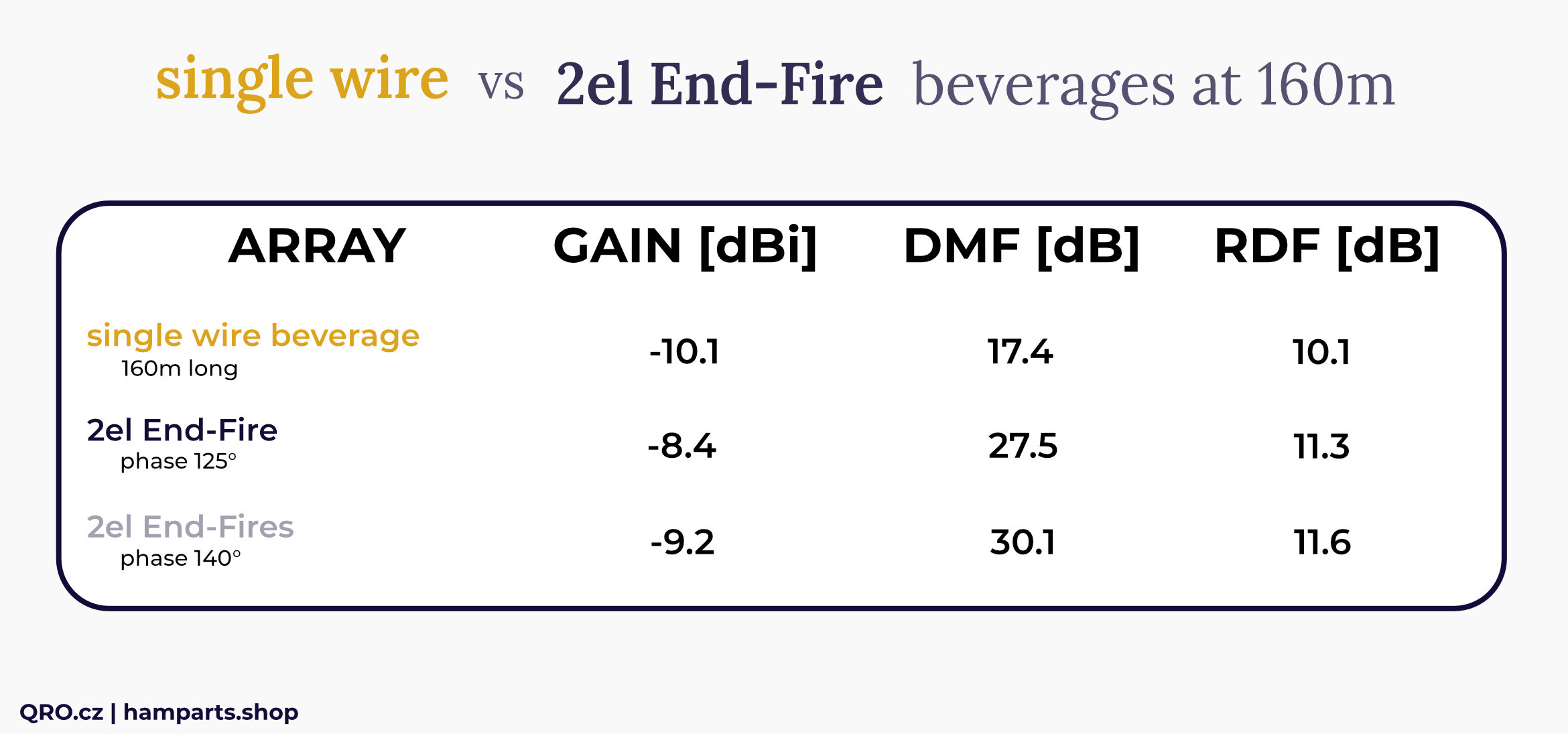
2el End-Fire beverage antenna array manual
The beverage is a long wire antenna installed very close to the ground. The antenna should be longer than 1 wavelength and installed at a height of less than 0.05 wavelength above ground. The beverage is usually terminated in a resistance at the end (opposite the feedpoint). Beverage antennas provide one of the least expensive and most reliable ways to improve DX capabilities on the low frequencies.
source: ON4UN LBDX
Jump to
Applications
Building
Example for Tri-band array
Simply working configuration
Comparisons
Comparison of arrays for 80m
KIT assembling
Video
Product details
Applications
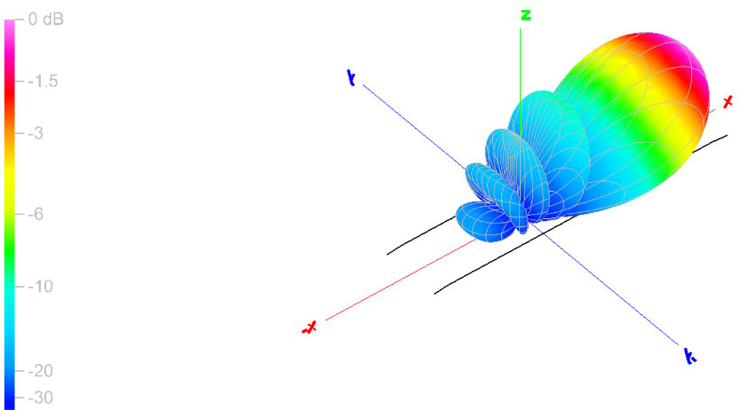
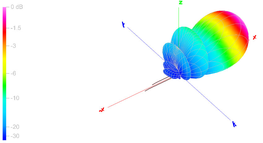
If you are after improved directivity in the rear of the antenna (improving the DMF), you can put up two beverages fed as an end-fire phased array. The beverages you wish to phase together need to be identical (same height and length). In an end-fire beverage array it is important that the two elements have a similar F/B, as you are going to subtract the signals from both elements. You only get zero if you subtract two identical numbers. It does not matter what the numbers are though. Two beverages with a 10 dB F/B can produce 30 to 40 dB nulls in an array, just as much as a pair where the individual elements already show 25 dB F/B. (source ON4UN)
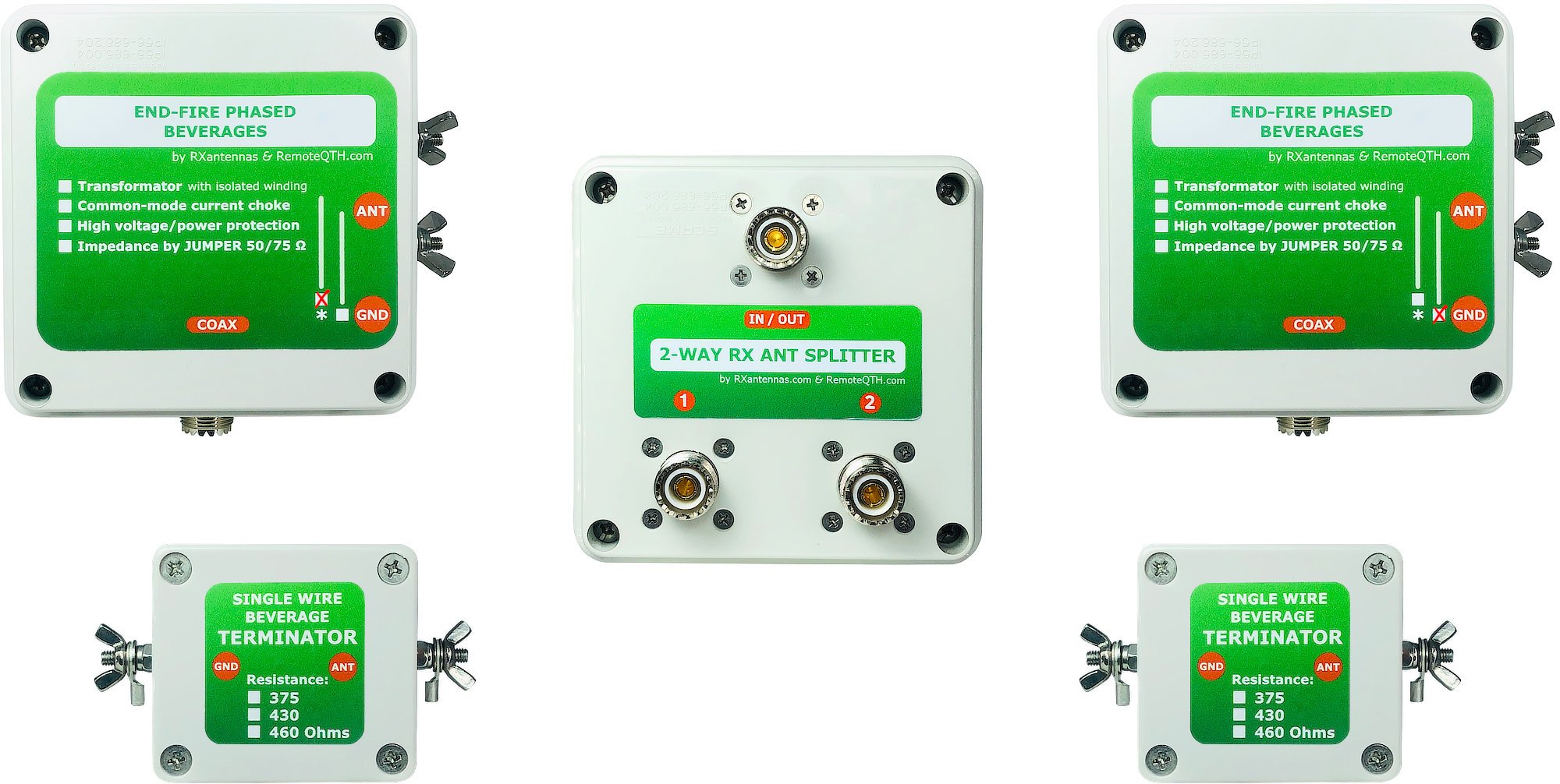
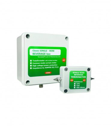
classic version with PL SO-239 connector
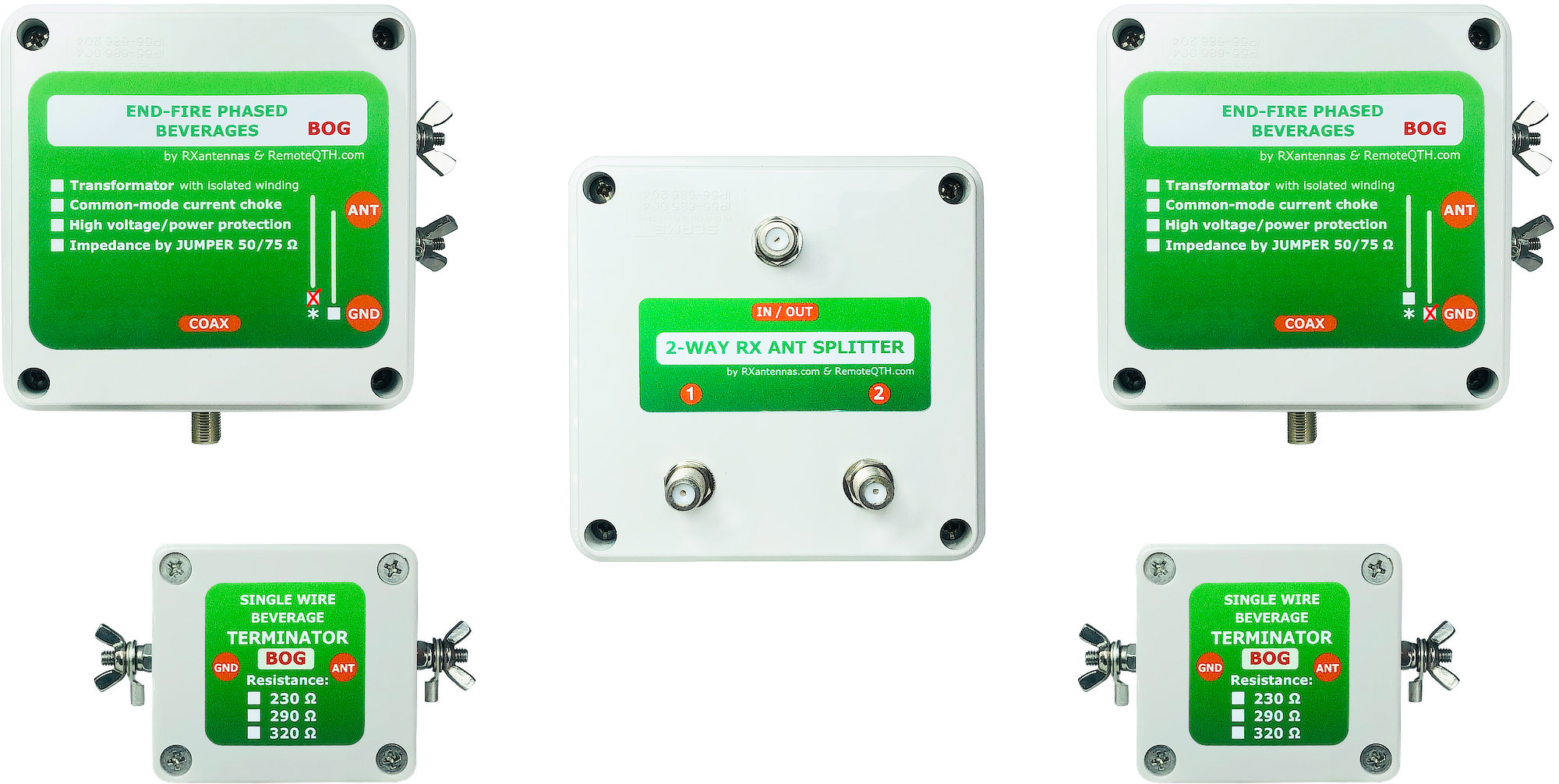
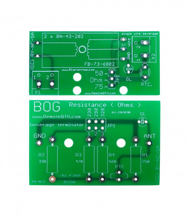
BOG version with F connectors
Building
- Use google and you can find a lot of very nice articles about the end-fire arrays
- I really recommend:
- Enhanced F/B beverages by W8JI
- Ideas for enhanced beverage antenna performance by N2NC
- And the best book called ON4UN's Low Band DXing at dx engineering
- Chapter 7 and 2.16.3. The End-Fire Beverage Array
- And some notes:
- Both antennas must be the same
- The same height and length
- Tune terminators to the best flat SWR - should be under 1 : 1.3 (on 50 Ohm feeder)
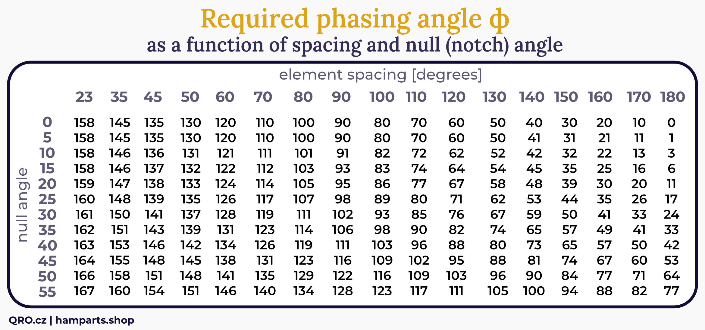
- Select null direction if needed from table
- Calculate phasing line
- Do NOT forget on: 2 * Length L + phasing line must be more than diagonal between feeders!
- Table with phasing lines vs. element spacing and NULL:
- Element spacing (degrees) = beverage stagger distance (20m distance on 160m band is 45°)
- NULL angle is angle you want to notch the signal from
- Result: Phasing angle for next calculations
source: ON4UN LBDX
Example for 3 band array
- Example by John ON4UN - source ON4UN's Low Band DXing (buy this book!) - Table 7-37
- from table chose Stagger distance for 20m - 20m is MAXIMAL distance which works on 160, 80 and 40m bands!
- chose space distance 2 to 6m
- from table chose NULL direction for unwanted signal
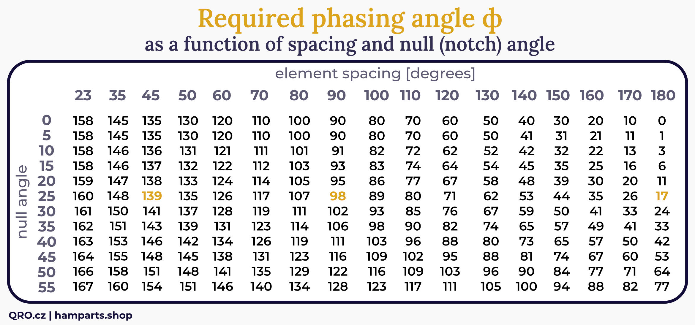
- from table: stagger distance 20m means element spacing (degrees) - 45° on 160m, 90° on 80m and 180° on 40m band
- NULL signal from 25°, then phasing angle will be 139°, 98° or 17° on each band
- than phasing line is 180° - phasing angle. 180° is done by one transformer in feeder box
- physical length depends on coax cable velocity factor (VF), for example RG-58 is VF=0.66
- so for needed 41° phasing line it is 12.34m
- calc: 300 / frequency (MHz) ➜ * VF ➜ / 360 ➜ * 41 = physical length (m)
- DO NOT FORGET to check diagonal length. For stagger and space distance (20 and 5m) it is 20.6m. There must be something more for connectors etc. There is some Length L line, which must be the same for both feeders and helps with better installation. Then is you use L = 5m then coax cables from feeders to 2-way splitter will be: first 5m and second 5m + 12.34m = 17.34m. Total diagonal length is 5m + 17.34m = 22.34m, we need more than 20.6m.
Simply working configuration
- Works on 160m, 80m and 40m band without any changes
- The biggest advantage of this antenna is F/B
- You usually do not need to null any signal from any direction
- Anyway it is not easy from calculations to real world
- So you can build this configuration, which works from 160m to 40m with very good parameters
- Spacing 2m to 6m (not critical, you can go up to 10m)
- Stagger distance 20m - must be the same on start and also end of beverage
- Phasing line coax 12.34m of RG-58. Length L 5m or more - must be the same on both sides
- Phasing line from different coax is dependent on VF of the cable
- Phasing line made from coax with VF=0.81 will be around 15.2m
Comparisons
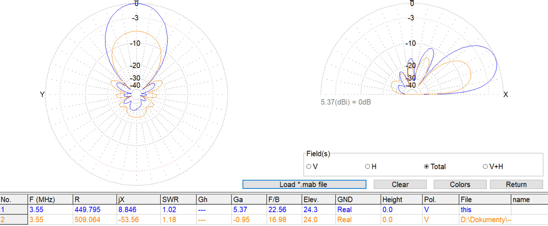
Comparison of array for 80m
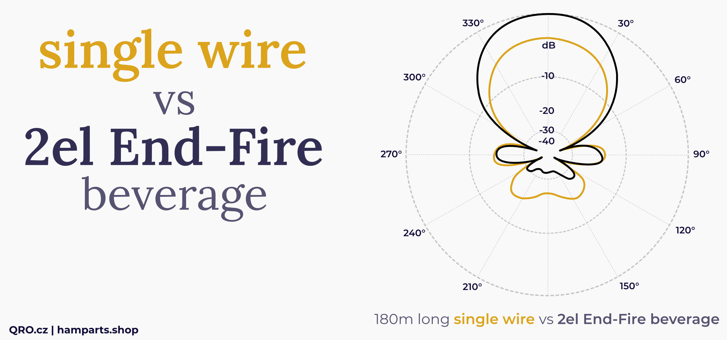
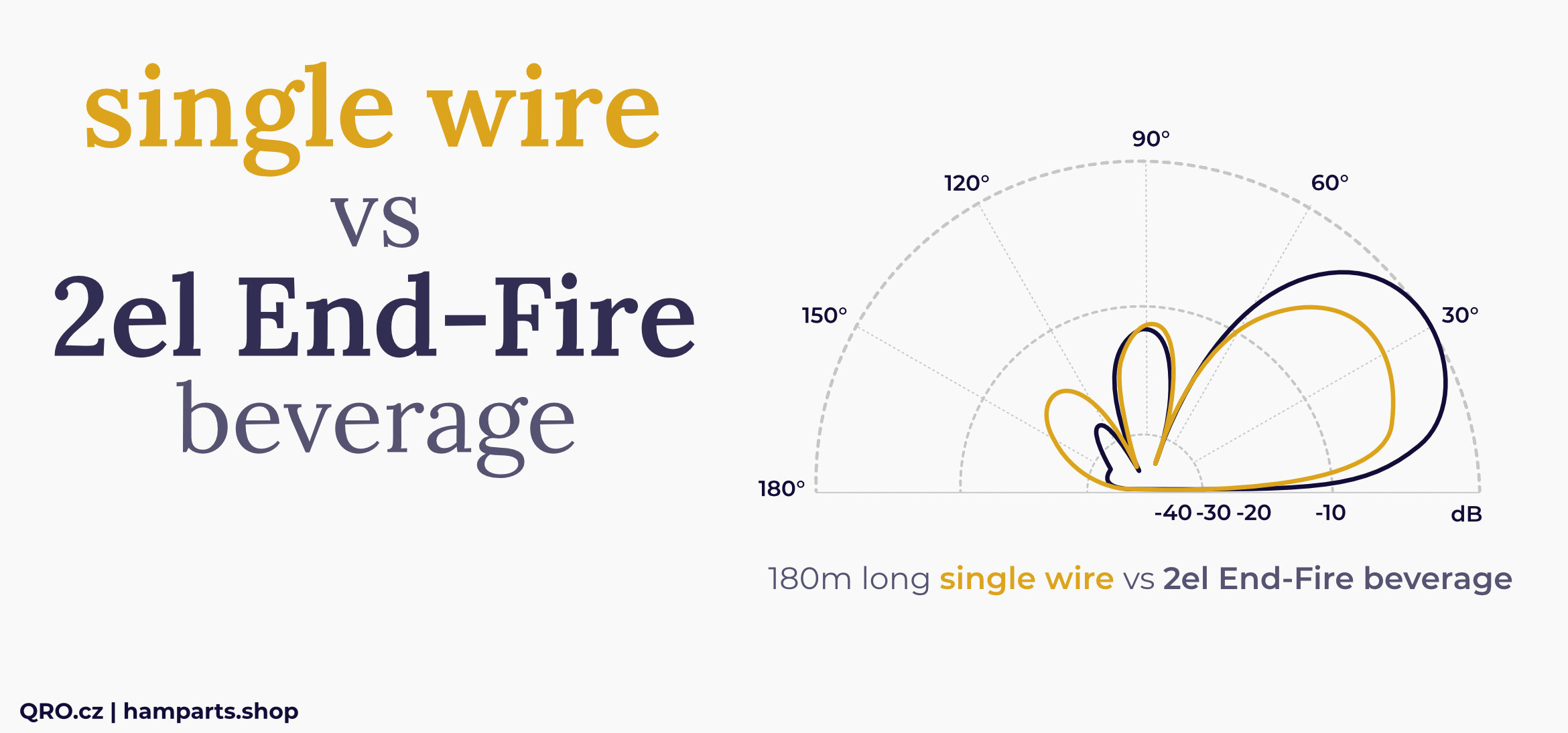
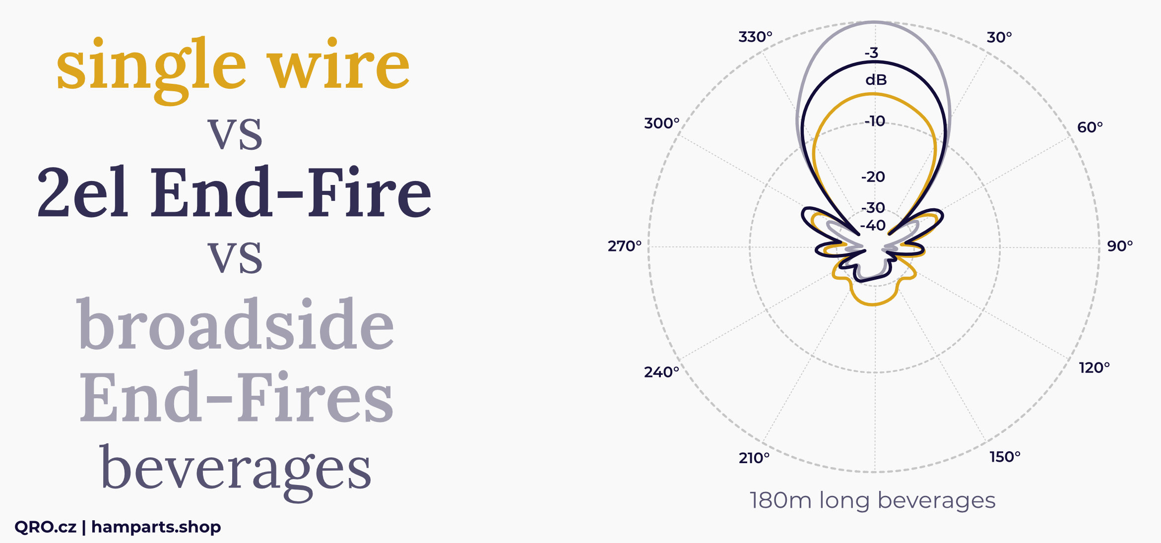
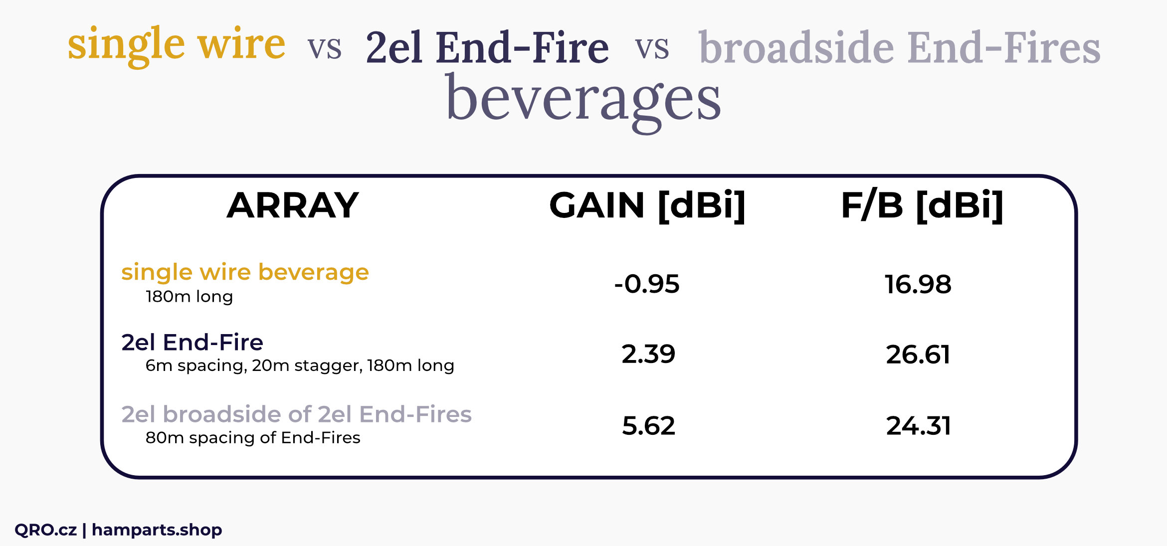
- Example with 180m long beverage compare to arrays
- 2el broadside with 180 long beverages and 40m spacing
- 2el End-Fire with 6m spacing and 20m stagger distance. Phasing 84 deg.
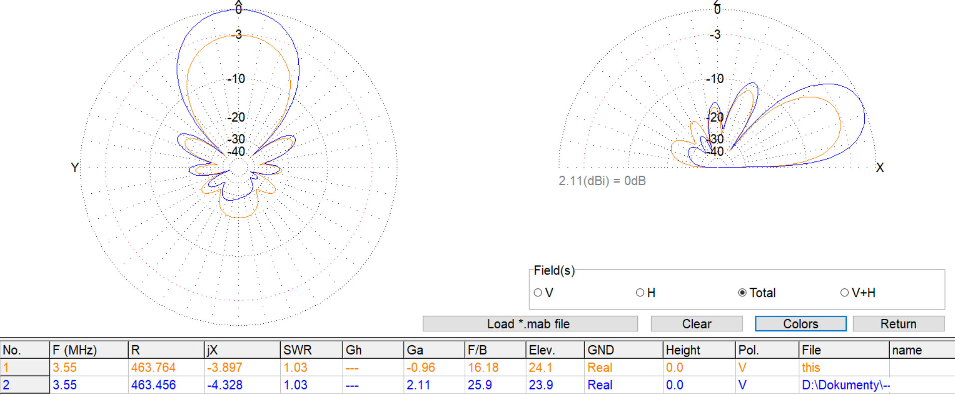
Compare Single wire beverage (1) and 2el End-Fire array (2)
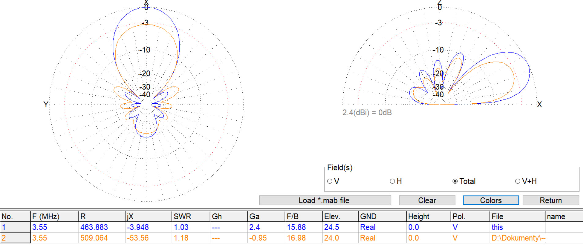
Compare Single wire beverage (2) and 2el broadside array with 40m spacing (1)
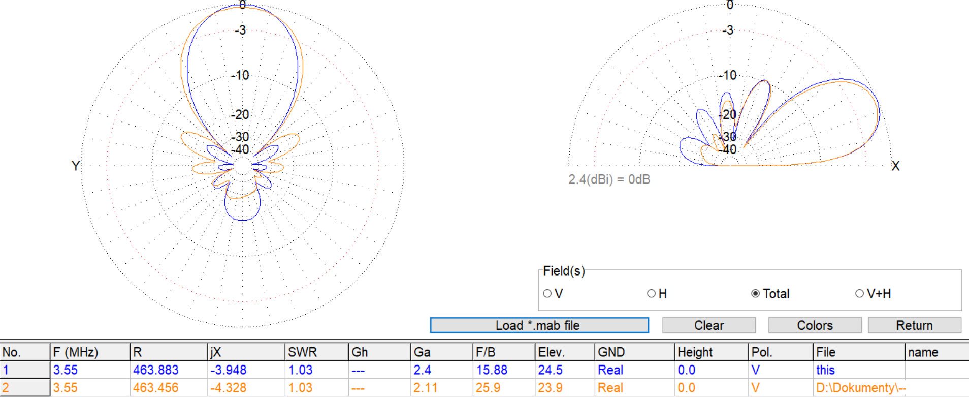
Compare 2el broadside array with 40m spacing (1) and 2el End-Fire array (2)
2el broadside array
2el End-Fire beverage
Ultimate RX antenna array. Two element End-Fire beverages in broadside configuration with 40m spacing
Compare Single wire beverage (2) and 4el End-Fire array in broadside configuration (1)
KIT assembling
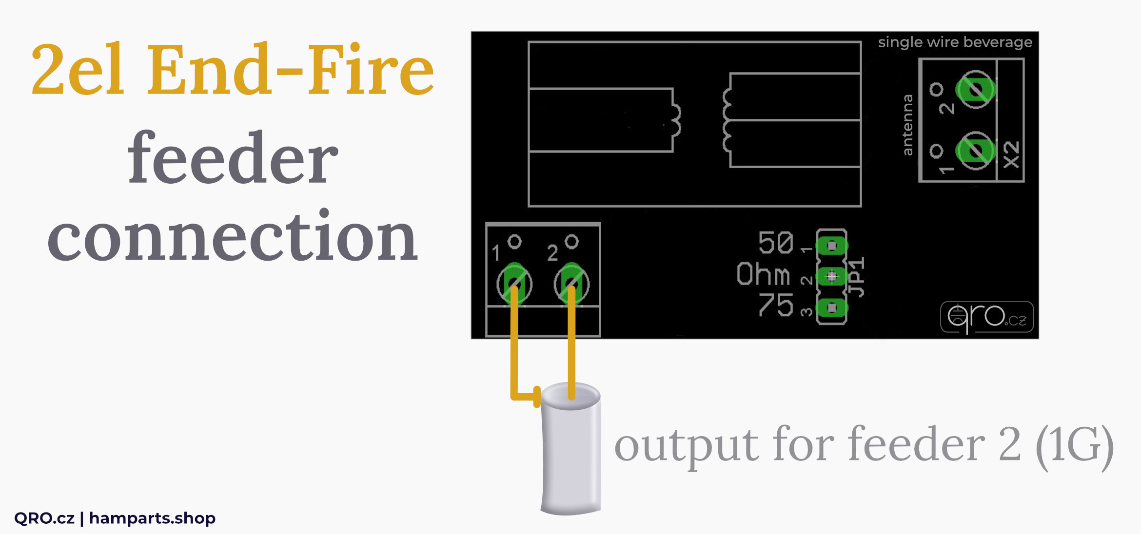
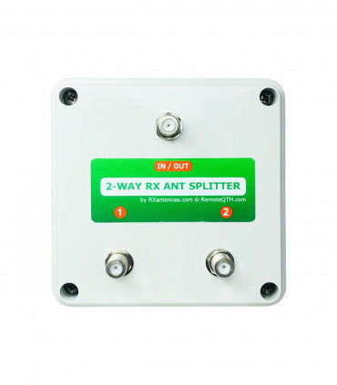
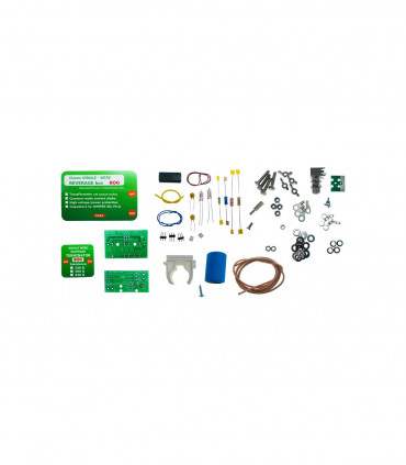
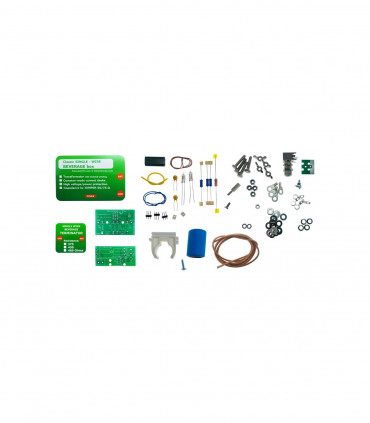
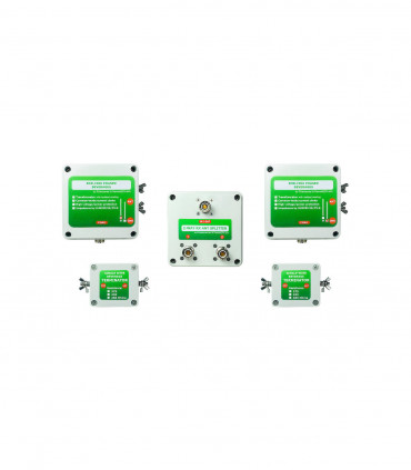
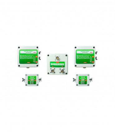
- A KIT contains three parts: 2-way splitter BOX and two Single wire beverages
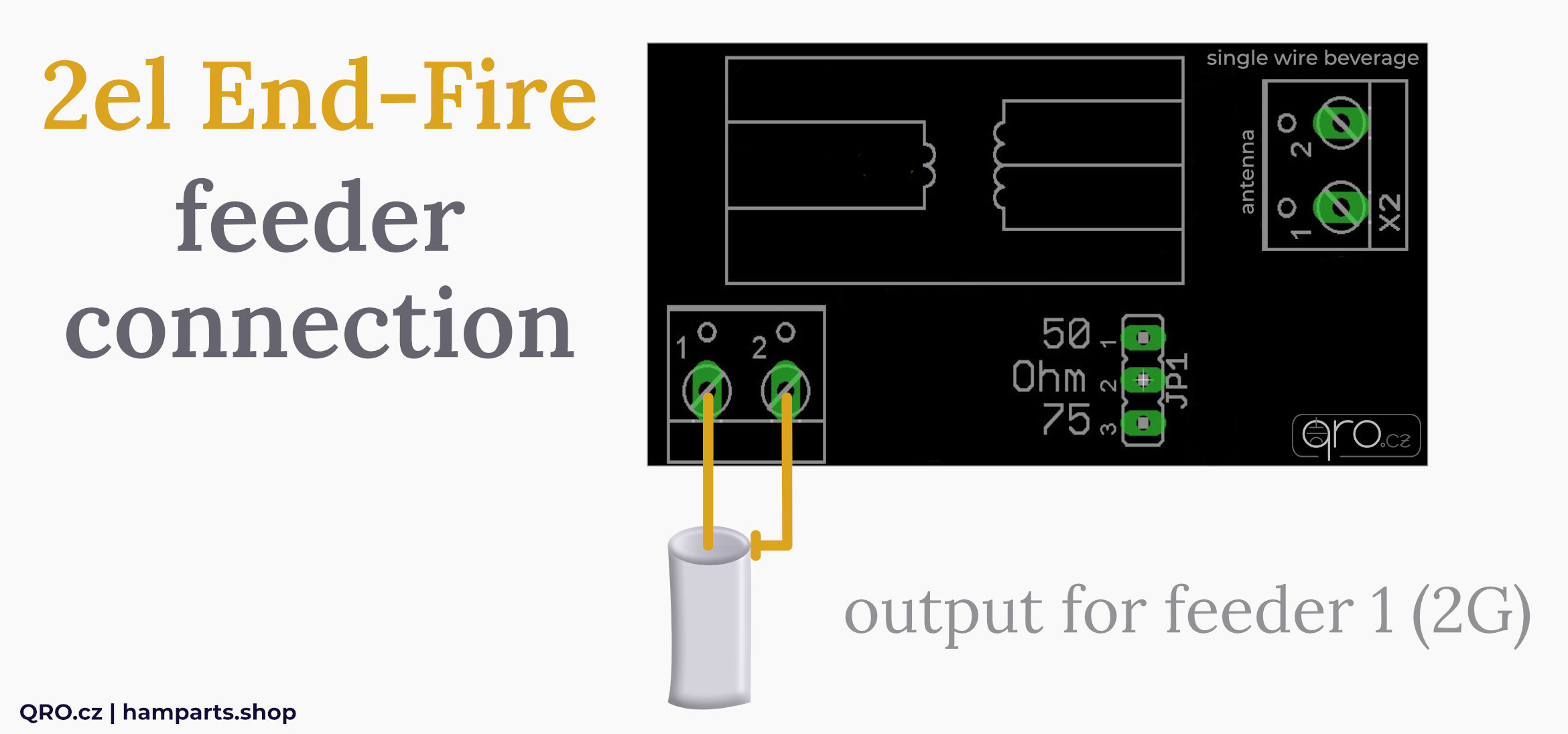
- Before you start building single wire beverages, please keep in mind that there must be 180 degrees phase shift between each other
- This is made by different output coax connection
- Please continue to manuals for 2-way splitter and single wire beverage CLASSIC and BOG version
have a look at these pictures and do right coax connection
Video by VE6WZ
ℹ Watch video from Steve Babcock, VE6WZ.


