3-way active splitter manual previous
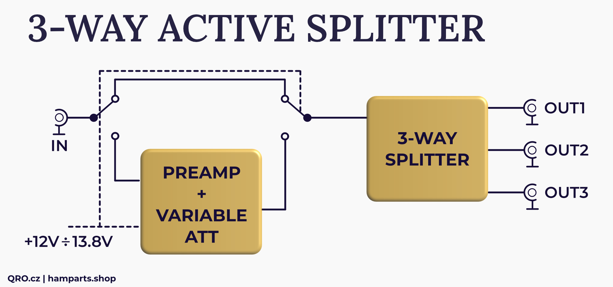
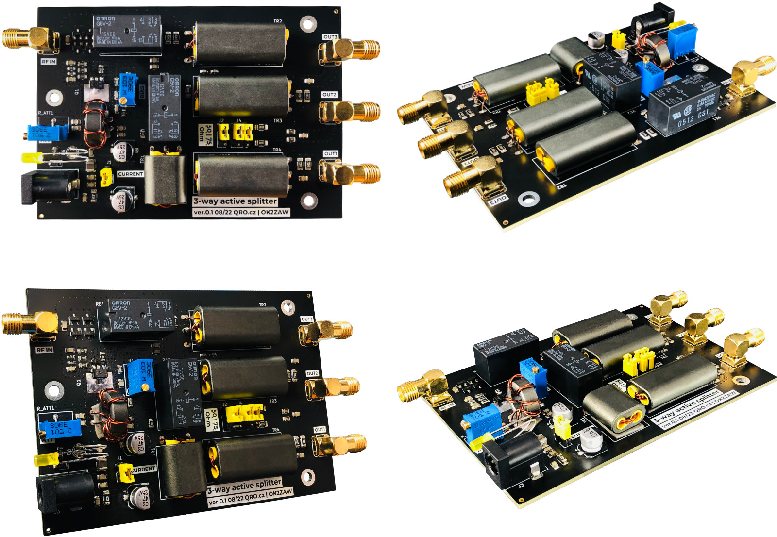
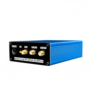
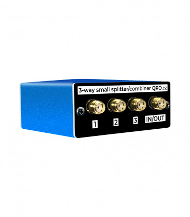
This device is a combination of a passive 3-way splitter and a High IP3 preamplifier. The passive 3-way splitter splits the input signal into 3 outputs with very good matching and high isolation. The preamplifier compensates for the insertion losses of the passive splitter. Thanks to the variable attenuator you can adjust the gain as you need. Impedance of the splitter can be selected by jumpers 50 or 75 Ohm.
NOTE: This HW is designed only for RX line.
Jump to
Applications
Splitter
Tune and test points
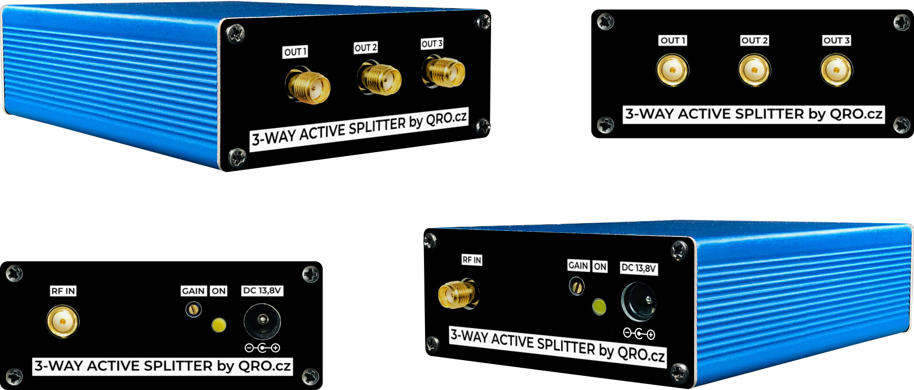
Product details
Applications
Block diagram for 3-way active splitter
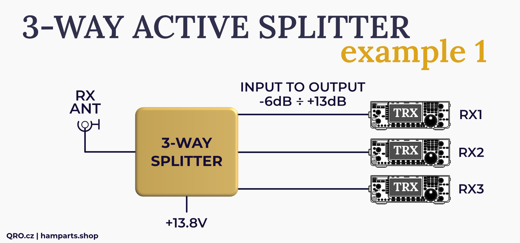
Example for one antenna to three receivers
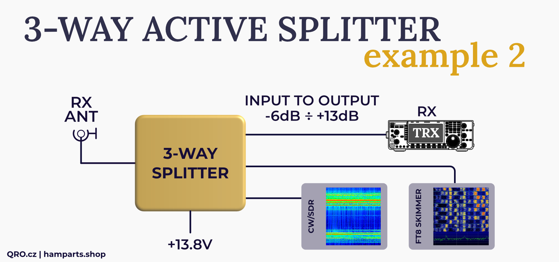
Example for one antenna to RX and SDR as a skimmers
Splitter
Tune and test points
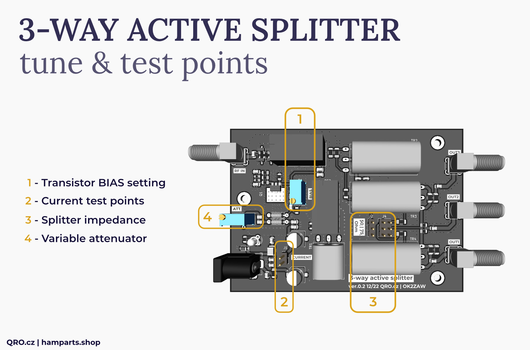
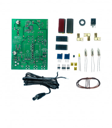
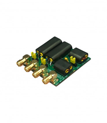
There are two trimmer resistors which allow you to set gain (variable output attenuator) and bias of transistor. Bias is preset to 40 mA at 13.8 V. Jumper with the test points for transistor current check and jumpers for splitter impedance switching between 75 and 50 Ohm.
1. Transistor BIAS setting
- this is trimmer (BIAS R4) which sets transistor bias current
- higher current means higher IP3
- recommended is 40 to 50 mA - higher currents need better cooling
- with bias current around 15 mA, the noise figure of the preamplifier is around 1
- for setting this bias current open jumper JP1 and measure it there
2. Current test points
- remove jumper (JP1)
- connect mA meter there (200 mA scale is fine)
- connect supply voltage
- turn the resistor trimmer (BIAS R1) and set bias current you want
- then connect jumper short back again
3. Impedance of the splitter
- You can switch between 50 and 75 Ohm by the jumpers J2 and J4
4. Variable attenuator
- by this resistor trimmer you can set preamplifier gain as you need
- CW direction = higher ATT value = lower gain
- CCW direction = lower ATT value = higher preamplifier gain

