


116.16 €
(tax incl.)
96.00 €
(without tax)
RF switch controlled by AC or DC voltage over coax
select the delivery location, based on the selection, the sales prices and delivery costs will be recalculated

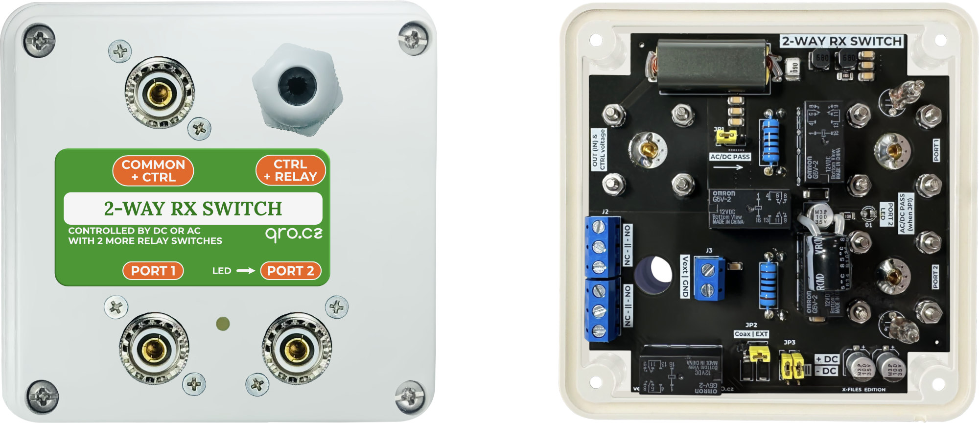
This is 2-way switch for RX system. It allows you to switch two RX RF signals from two inputs to one output. The unused input is loaded with an internal dummy load. There are several ways and signals to control the switch. It can be switched by voltage over coaxial cable, external signals and also use two relay contacts to switch other signals - preamp power, audio path, etc.
The voltage coming through the coaxial cable can also be sent to the input to power, for example, an active antenna.
Applications
Switch
Block diagram
Jumpers
Control Voltage
Voltage passthrough
Optional relay contacts
Examples of use
Measurements
Product details
- 2-way switch - two inputs to one output
- 2-way switch - one input to two outputs
- 4-way Bi-Directional middle switch
- Voltage pass through for active antenna
- Switch for two SDRs and audio path
- see Examples
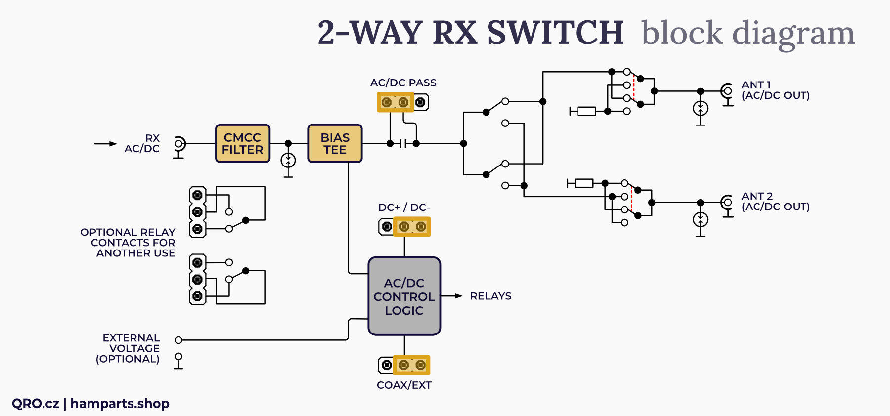
A look at the block diagram will allow you to understand the principle of the device. The two input ports contain surge protectors and the unused input is connected to a load resistor - 50 Ohm 2 W. Due to the design, the switch achieves a high isolation between the inputs and at the same time a low pass-through attenuation. The bias tee is used to obtain a voltage from the output coaxial cable. This voltage can be used to control the switch. By using a jumper it is possible to send this voltage further to the input to power e.g. the active antenna (more in Examples).
The switch can also be controlled by the voltage applied to the internal screw terminal connector. Jumpers can be used to select ow the switch is controlled and with which voltage: +DC, -DC or AC. The two relay contacts can be used to switch external signals or voltages. For example, blocking, powering another preamplifier or audio path between SDR receivers.
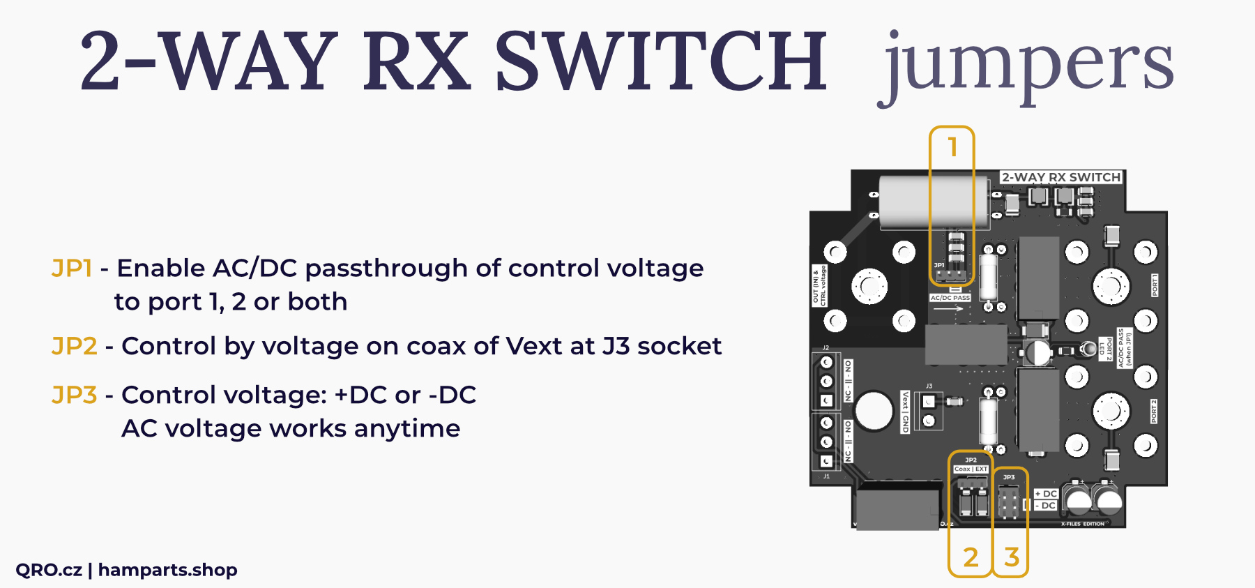
- Enable AC/DC passthrough of control voltage to port 1, 2 or both. See more there
- Control by voltage on coax or Vext at JP3 socket
- Control voltage: +DC or -DC. AC voltage works anytime
This switch is controlled by voltage 12 to 15V AC or DC. You can use interbal Bias tee and control switch over the coax cable. There i salso J3 socket which can be used directly. This switch allows you to set what polarity is sensitive to. There can be selected +DC or -DC by the jumper JP3. This means that the switch will select port 2 when you apply +DC or -DC or AC. Depends on JP3. Do not forget – switch will select port 2 with AC voltage anytime!
You can enable this feature by jumper JP1. With advantage you can supply active antenna or external preamp. Depends on configuratin, there can be this options:
1. 2-way switch is controlled by +DC:
- You can use active antenna or preamp (supplied over the coax) at port 2
- When you apply +DC voltage, switch will select Port 2 and when jumper JP1 is in right position, you will have +DC voltage or at port 2 (Example 3)
2. 2-way switch is controlled by -DC:
- You can have active antenna at port 1
- Positive voltage at coax will not select port 2 but you can have this voltage at the output of the switch at port 1 and use it for active antenna or preamp
- When you apply -DC voltage, switch will select port 2 and this negative voltage will be at port 2. So you have to count with it and connected antenna (device) must have DC blocking at coax or must count with this voltage
- When AC voltage is applied, switch will select port 2 and AC voltage could be also at port 2 coax when JP1 is in right position.
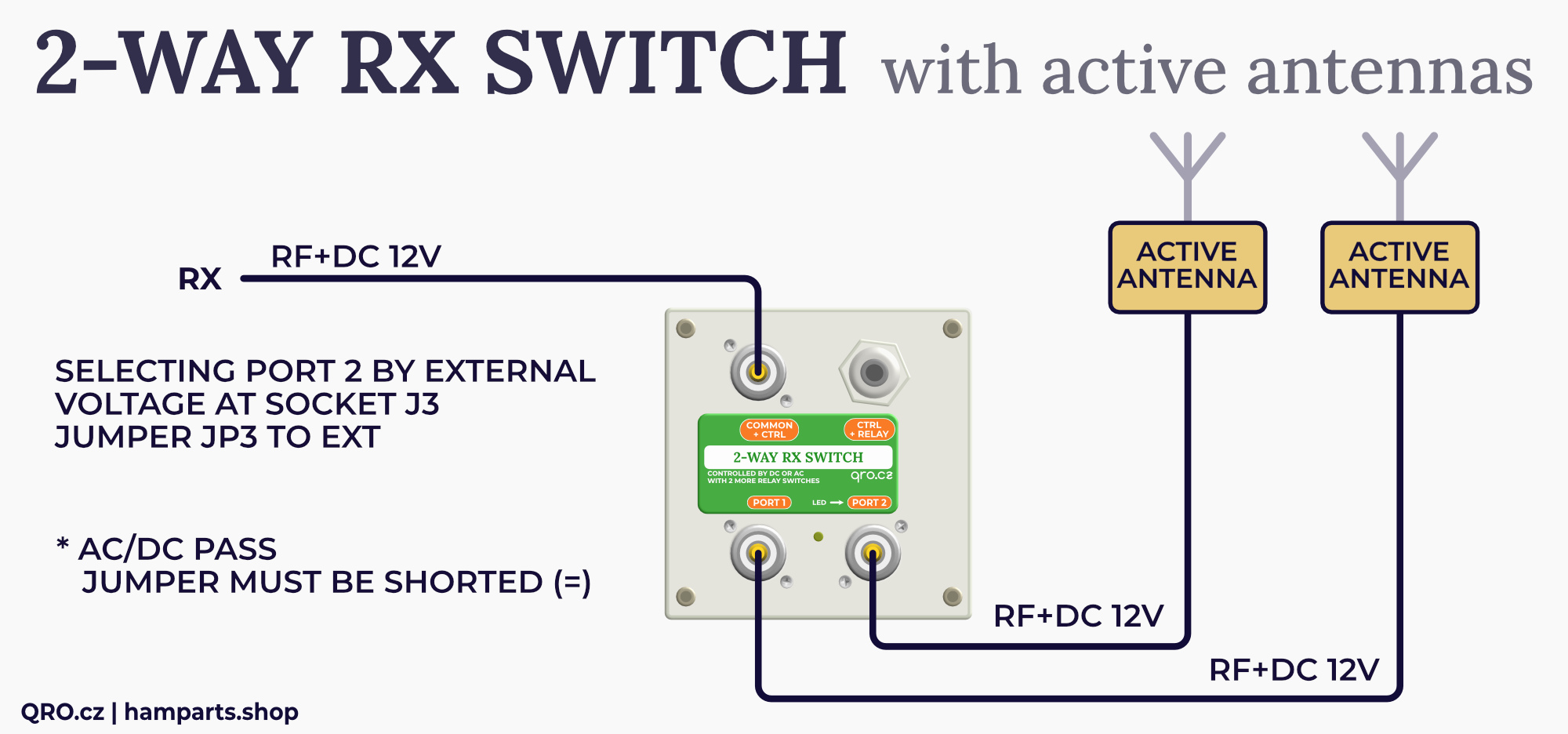
3. 2-way switch is controlled by External voltage at socket J3 (Example 7)
- In this example you can use two active antenna and common port as bias voltage for selected one. Selecting port 1 or 2 is done by external voltage at J3 socket.
- Enable AC/DC pass - voltage from common port could go to both ports (1 or 2)
- Jumper JP2 set to EXT (control voltage at J3 socket)
- Jumper JP3 usually to +DC.
When JP1 is in left position, there is AC/DC blocking and there is no voltage at port 1 or 2. Anyway you have to count with some AC „noise“ voltage which can go over blocking capacitor. When you use Receivers at port 1 and 2 and control 2-way switch by AC, please do not use SDR without band pass filters or use high pass filter 10kHz+ to protect SDR from AC noise.
⚠ IMPORTANT NOTE: Switching voltages over the coaxial cable can result in an annoying "click" in the receiver. This is due to a current spike at the relay contact. This can be annoying, especially if you switch frequently. Also, when the AGC on the receiver is set to SLOW it can cause the receiver to "close", for the duration of the AGC constant.
There is one more small signal relay with two contacts. These sockets J1 and J2 can be used for external devices. You can use it for:
- Switching audio way between two receivers (Example 4)
- Switch voltage for preamps
- Select some protection for port which is not used etc.
This is small signal relay, please do not you current higher than 1A and voltage over 60V.
Example 1: 2-way switch for 4-way/K9AY controller
This is an example where this box is used as a 2-way switch with AC/DC voltage through coaxial cables. The switch is controlled by an external voltage applied to connector J3.
Jumpers must be set: JP2 to EXT, JP3 to +DC (+12V control) and JP1 in the right part (AC/DC PASS)
In this case, the voltage goes further along the coaxial cable, to other boxer - Bi-DIR feeder (direction switching), 4-way Bi-DIR Beverage RX switch or another this 2-way RX switch in the same function.
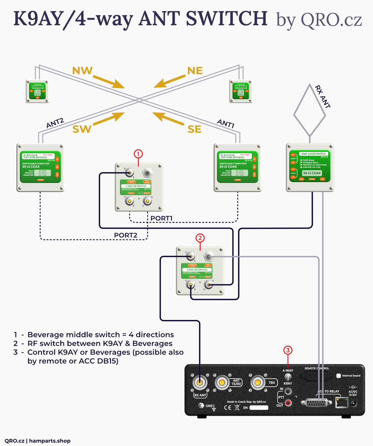
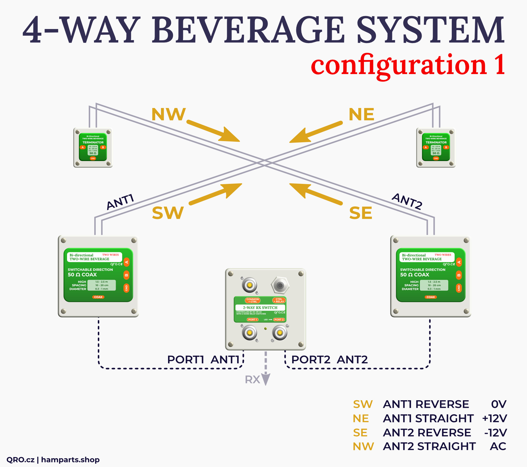
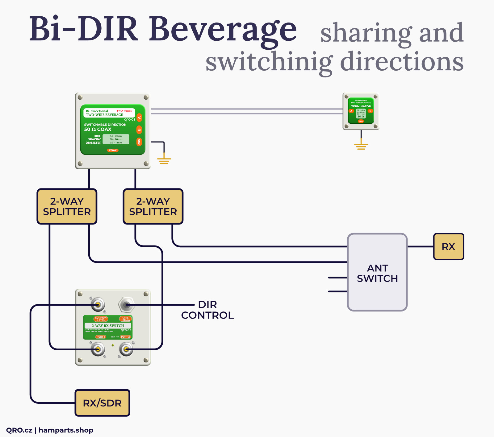
Example 2: 2-way switch for two Bi-DIR Beverage antennas = 4 directions
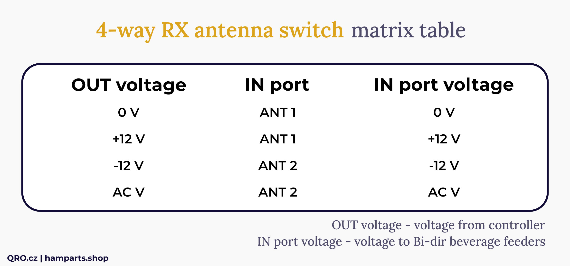
This is an example where Bi-DIR Beverage antennas are controlled by a positive DC voltage (+12V). The middle 2-way RX switch is set to be controlled by a negative DC voltage (-12V). Then it is possible to control 4 directions using 3 voltages.
Of course, you can also use Bi-directional Beverage antennas that are controlled with negative DC voltage and control the 2-way RX switch with positive DC voltage. You can find more: technical article Where are your feeders?
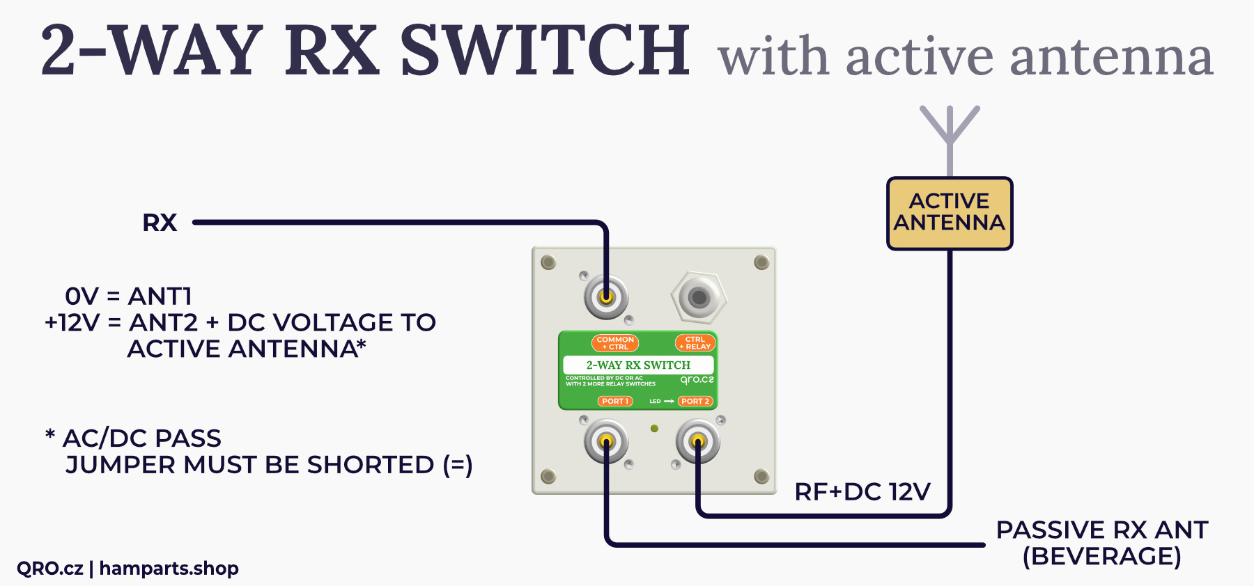
Example 3: Switching with one active RX antenna (MiniWhip)
If you are using an active RX antenna, such as a MiniWhip or other RX antenna with a preamplifier, you can use the AC/DC PASS function to send the voltage further down the coaxial cable.
If there is one active antenna, you can connect it to Port 2, set the switch to DC+ (jumper JP3) and jumper JP1 on the right. Then, after supplying +12V over the coaxial cable from the RX, the 2-way RX switch (indicated by the LED) and the voltage will continue through Port 2 to the active antenna. This will only feed and amplify the antenna when the switch is flipped.
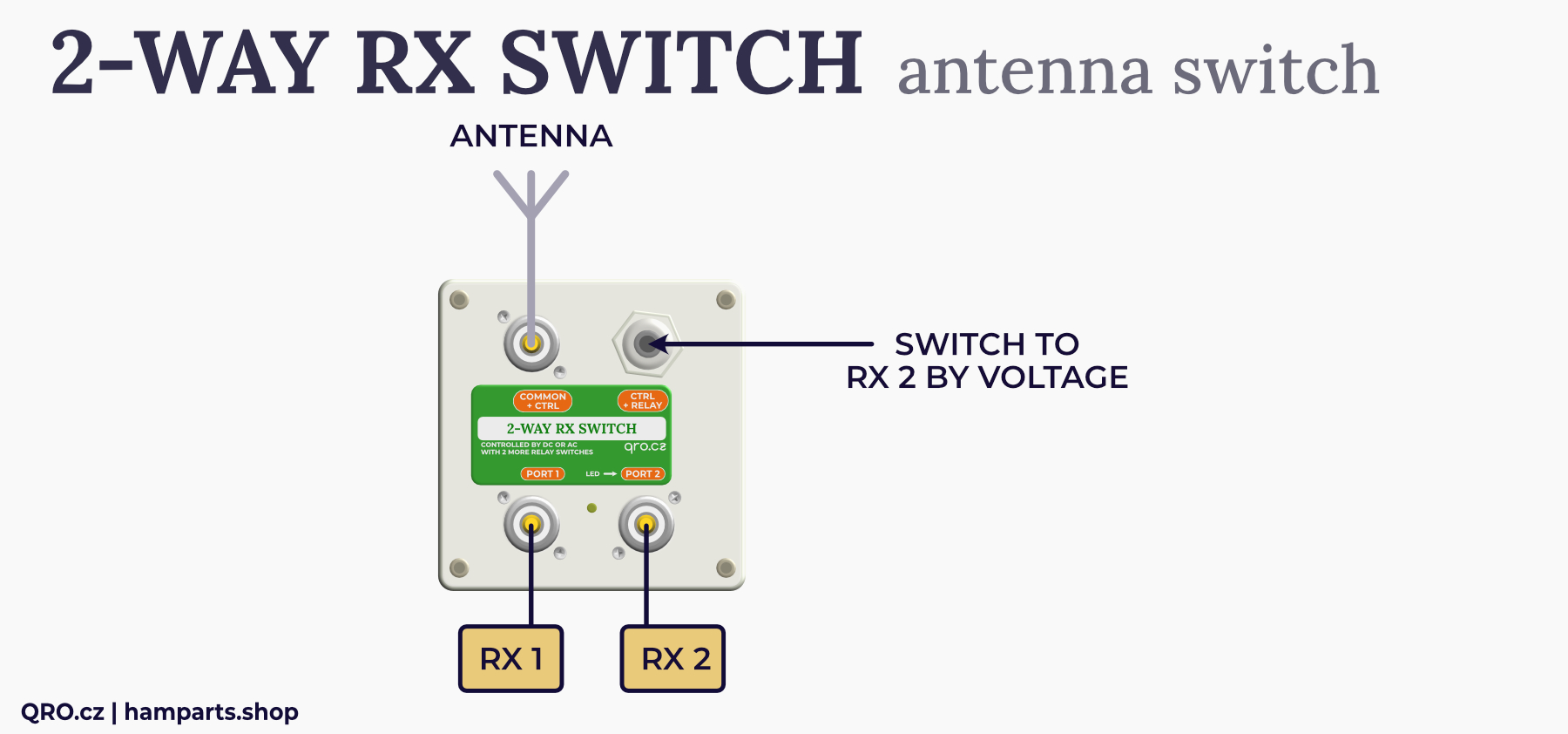
Example 4: Classic 2-way RF switch for RX
As a classic 2-way switch for two inputs to one output or one input to two outputs. Controlled by a single signal to switch to PORT2.
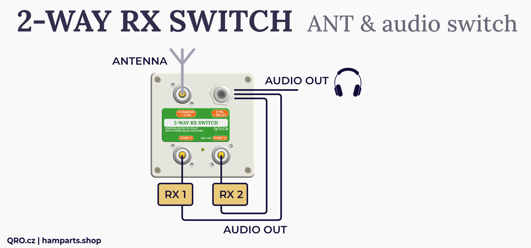
Example 5: 2-way RF switch + Audio switch
The switch contains one relay with two switching contacts. These can be used to switch external signals.
This can be used, for example, to switch audio from two receivers.
You can use the 2-way RX switch to switch one antenna between two receivers. In case the antenna is connected to one receiver. You can also use this relay to switch the speaker.
Example 6: Direction switch for Bi-DIR with 2 coax outputs
Bi-directional Beverage with 2 outputs is a handy thing for Multi RX - sharing antennas and directions. If you only need one coax, a dummy load switch on the unconnected input is recommended. This 2-way RX switch includes internal dummy loads of 50 Ohm 2W on the unconnected port. Using the voltage on the coax cable you can then switch direction.
Example 7: Two active antennas, selected one is powered over coax cable from common bias voltage at coax cable (one common Bias Tee)
This example illustrates the use of a switch with two active antennas or two preamplifiers. Where these active elements are fed over a coaxial cable and only the one switched by the switch is active. The voltage on the coax is only used to power the active amplifiers, not for switching. The selection between ports 1 and 2 must be made using the voltage on the internal connector J3.
The settings in this case will be:
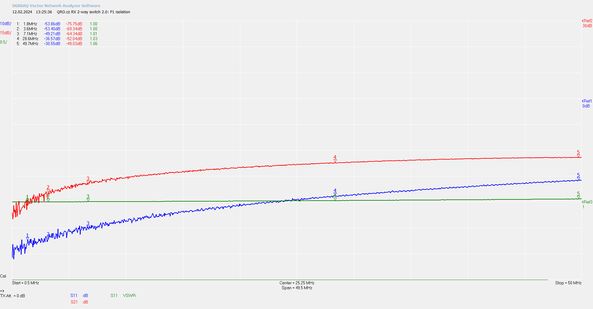
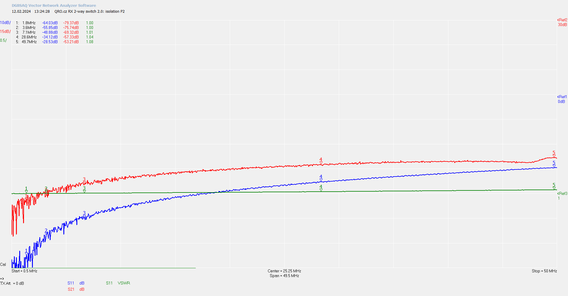
Port 1 Isolation
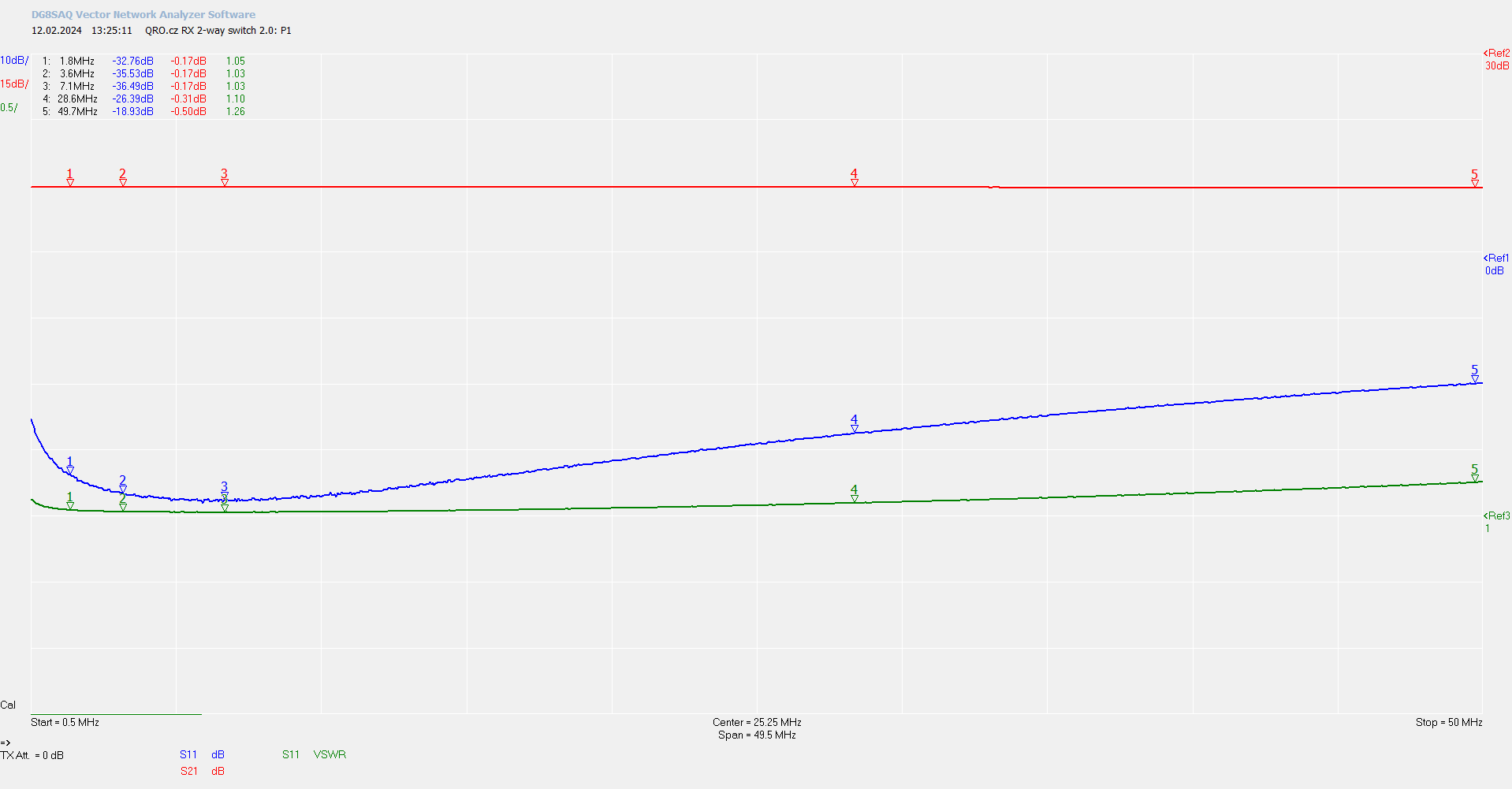
Port 1 SWR and IL
Port 2 Isolation
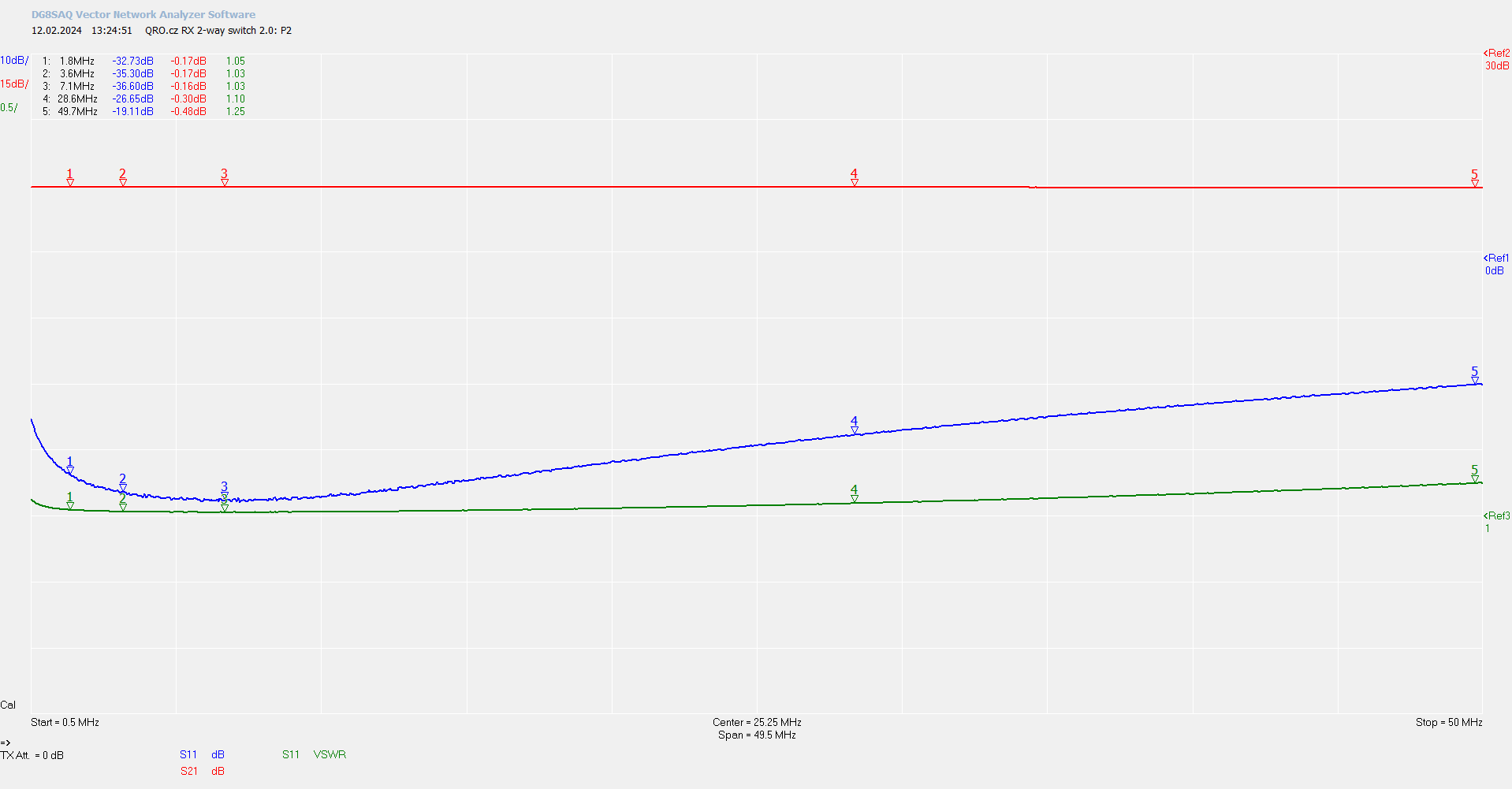
Port 2 SWR and IL
Product details
Switch assembled and tested
| Box dimensions (mm) | 100x100x50 - PU box IP56 |
|---|---|
| Weight brutto (kg) | 0.39 kg |
Ing. Jan Šustr
ID 05476356, VAT CZ8407024780
Palachova 1777/7, 591 01 Žďár nad Sázavou, Czech republic, Europe
Please also read general instructions before handling the product.
ID 05476356, VAT CZ8407024780
Palachova 1777/7, 591 01 Žďár nad Sázavou, Czech republic, Europe
is compatible with the relevant Union harmonisation legislation directives:
EMC Directive 2014/30/EU
ČSN EN 61000-6-3 ed. 2
ČSN EN 61000-6-1 ed. 2 (333432)
On behalf of Ing. Jan Šustr (QRO.cz)
Ing. Jan Šustr, CEO
2nd December 2024
Please sign in first.
Sign inCreate a free account to save loved items.
Sign inCreate a free account to use wishlists.
Sign in