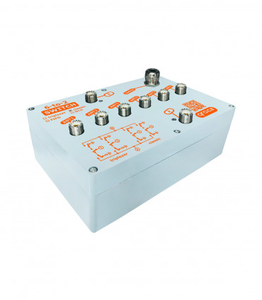
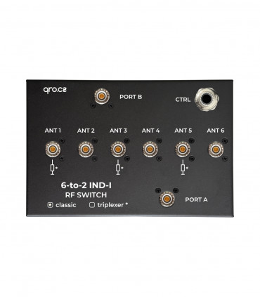
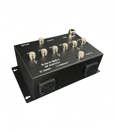
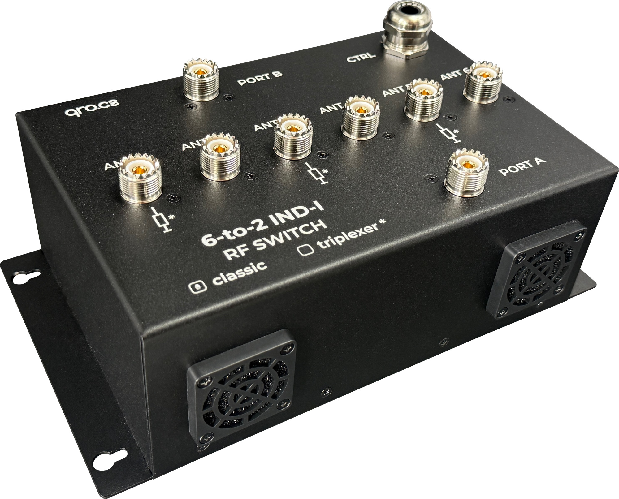
This is a variant of the popular six to two RF switch for SO2R designed for indoor installation or for installation in a protective box when installed outdoors. A fan has been added for better cooling. The RF board has been redesigned to achieve better parameters. The whole switch is engineered in a way that you just need to remove screws at RF connectors and the whole interior can be taken out of the box for inspection or repair.
In terms of performance, the switch can handle up to 4 kW on HF bands with good PSV. Thanks to the new PCB design, the switch can be used up to 70 MHz and 1 kW. There is a shielding plate between the RF board and the protective PCB.
The protection board allows you to control the switch using classic 6 wires for A (or B) and 6 ports or using BCD inputs. BCD inputs allow control over a wide voltage range, from TTL logic to 15V DC. LEDs indicate the status and enable better diagnostics. Another feature of this board is switch protection - first come, first served. The first to select a given port wins, and the second cannot use the same port.
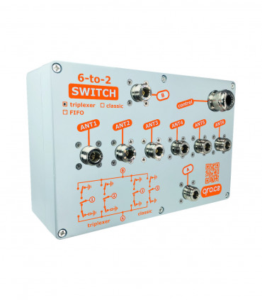
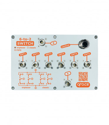
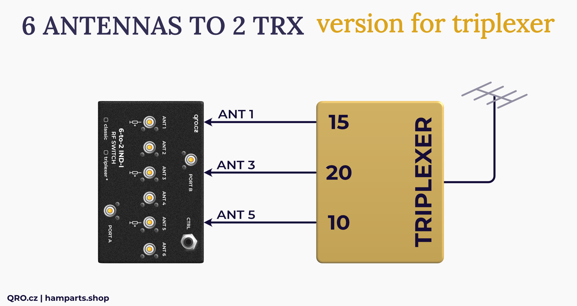
These instructions apply to both versions: classic and triplexer. The classic version means that unused ports 1 to 6 are grounded. The triplexer version grounds ports 2, 4, and 6. Ports 1, 3, and 5 have internal 50 Ohm dummy loads for 5 W RF power with protection against long-term overload - overheating and excessive power (100 W, etc.).
Jump to
Applications
Classic vs. Triplexer version
Switch Control - Connection
BCD control examples
LED indicators
FAN and cooling
Controller example
Parameters
Measurements
Product details
Applications
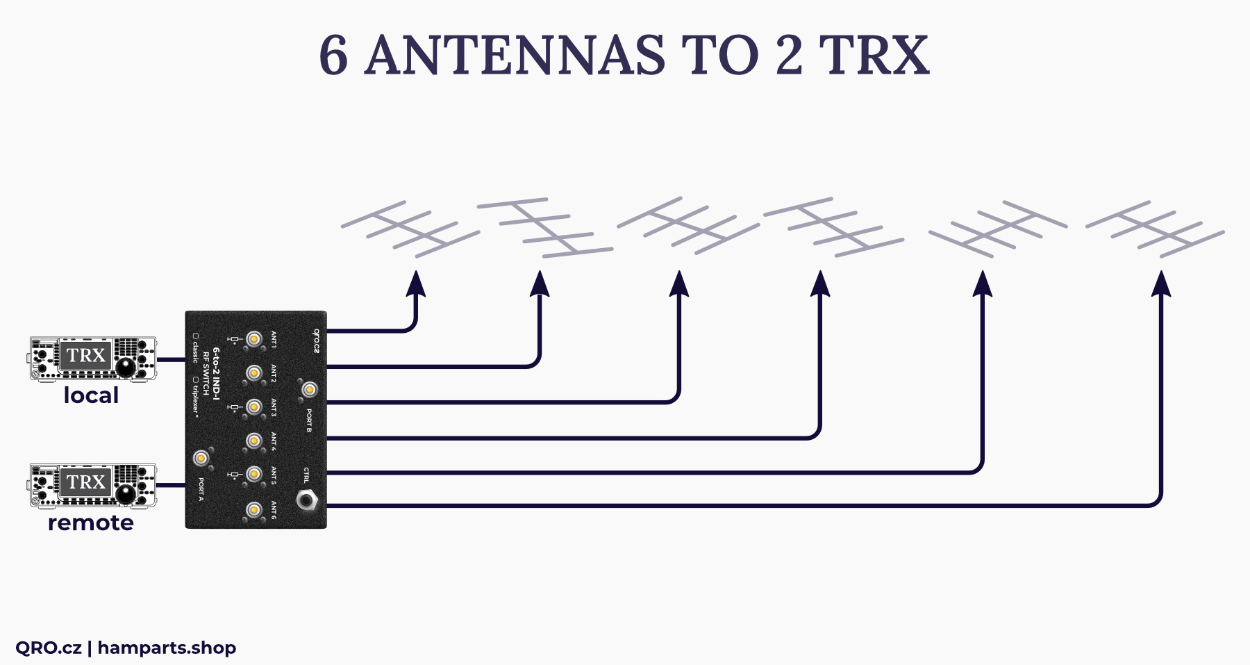
- SO2R antenna switch (2 TRX to 6 ANT)
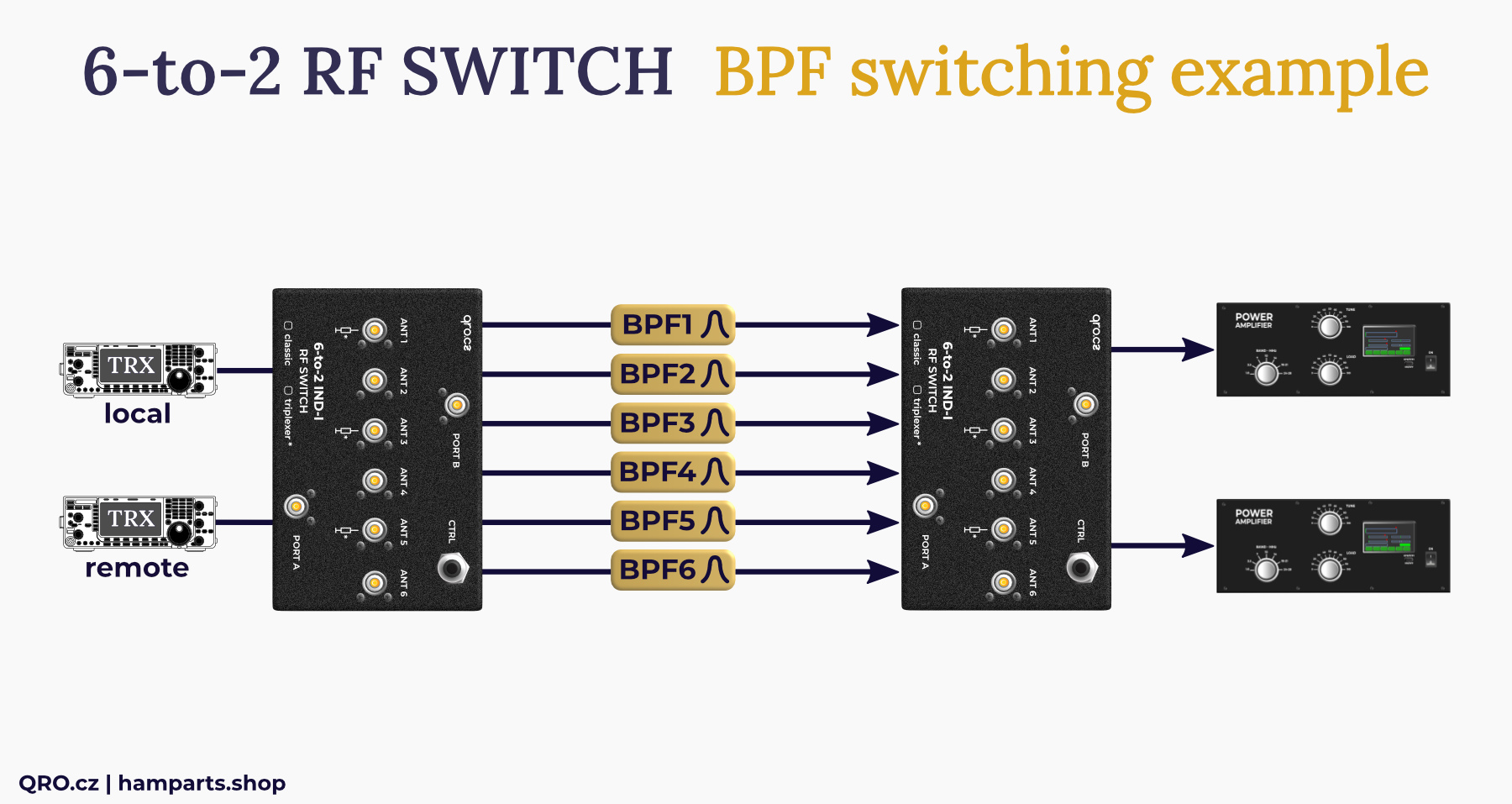
- BPF switch for 2 TRX
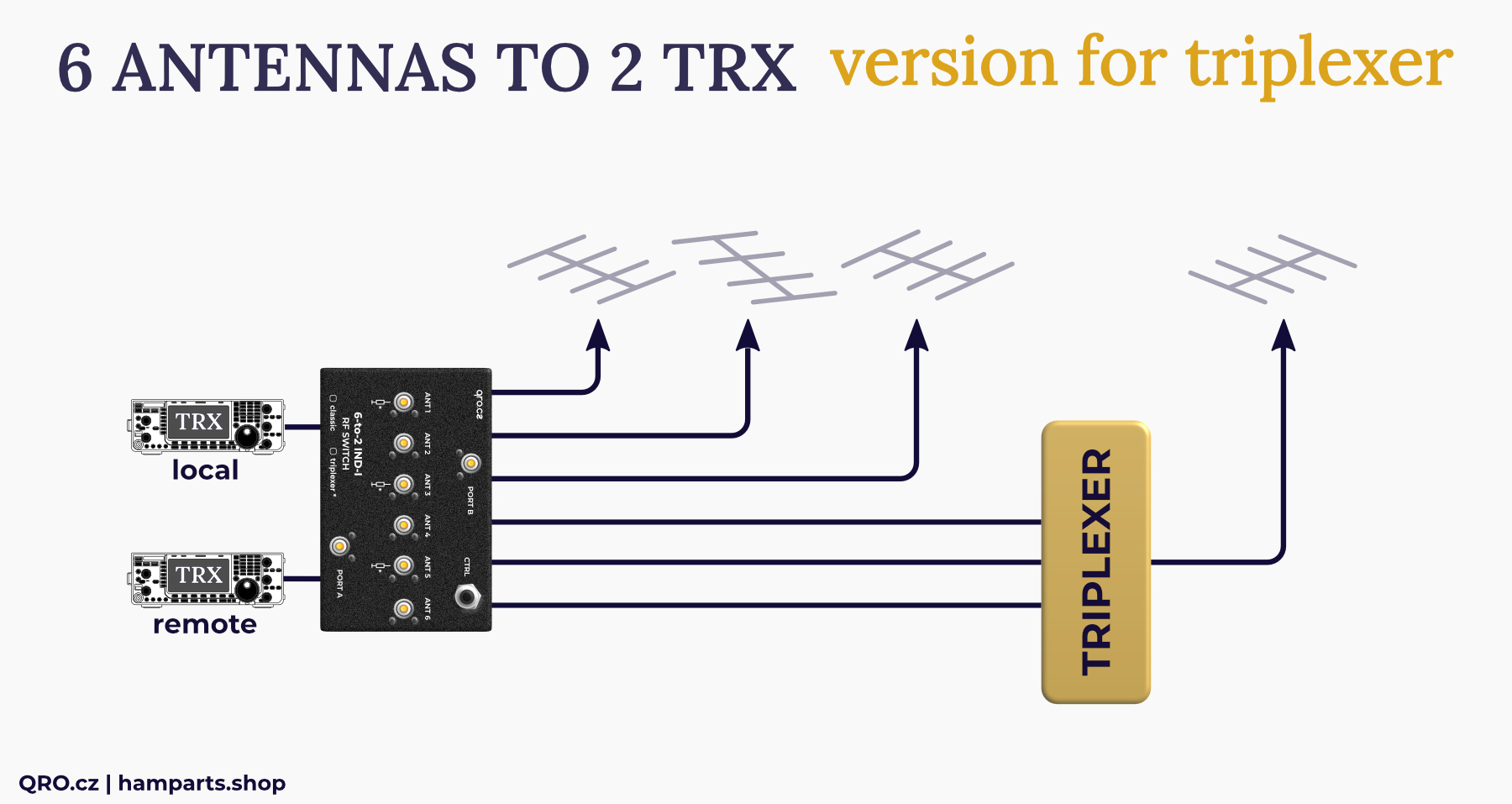
- 6 TRX to 2 antennas
Example for 2 TRX and 6 antennas
Example for Band Pass Filters switching for 2 TRX
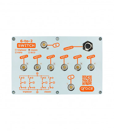
Classic vs. Triplexer version
The switches are available in two versions: Classic and Triplexer. The only difference is in the connection of unused ports. In the Classic version, unused ports are connected to GND. In the Triplexer version, ports 1, 3, and 5 are connected to an internal 50 Ohm dummy load, and ports 2, 4, and 6 are connected to GND. The Triplexer version is optimized for connecting a duplexer or triplexer that divides a multiband antenna into individual bands. If a given band is not in use, the port with the filter is loaded with a dummy load. This keeps the sideband suppression and SWR parameters of the duplexer/triplexer. GND or dummy load on the ports is connected even when the switch is off.
Switch Control - Connection
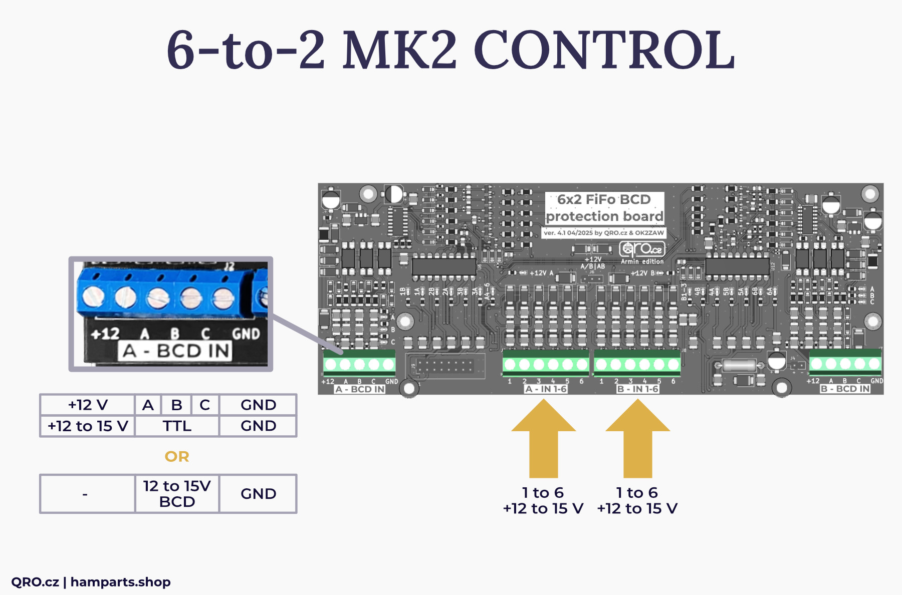
- It is possible to use connectors A - IN 1-6, B - IN 1-6 for conventional control over 2x6 wires (+ GND). The switch is controlled by + DC voltage > 12 V
- You can also use the BCD inputs A - BCD IN and B - BCD IN
- The switch uses binary combinations for 1 to 6. Again + DC voltage
- The BCD control has a voltage range from 3 V to 15 V. It is therefore compatible with TTL logic
- If you use TTL logic, it is necessary to connect also voltage for relay control - terminal +12 at BCD. The recommended voltage is 13.8 V. It is possible to supply this voltage separately for the A and B part. If the jumper (+12V A/B | AB) is switched to the A/B position, each half of the switch needs its own voltage (+12V at BCD). In this case, the part not in use may be without power. In the AB position, only one power supply to one of the +12 at the BCD connector is needed.
- If the BCD control voltage is higher than +13 V (13 to 15 V DC), you can use only the BCD + GND wires. The voltage for the relay is derived from the BCD control voltage.
- You can use BCD for one side and classic (conventional) control for second part.
Control connectors
BCD control examples
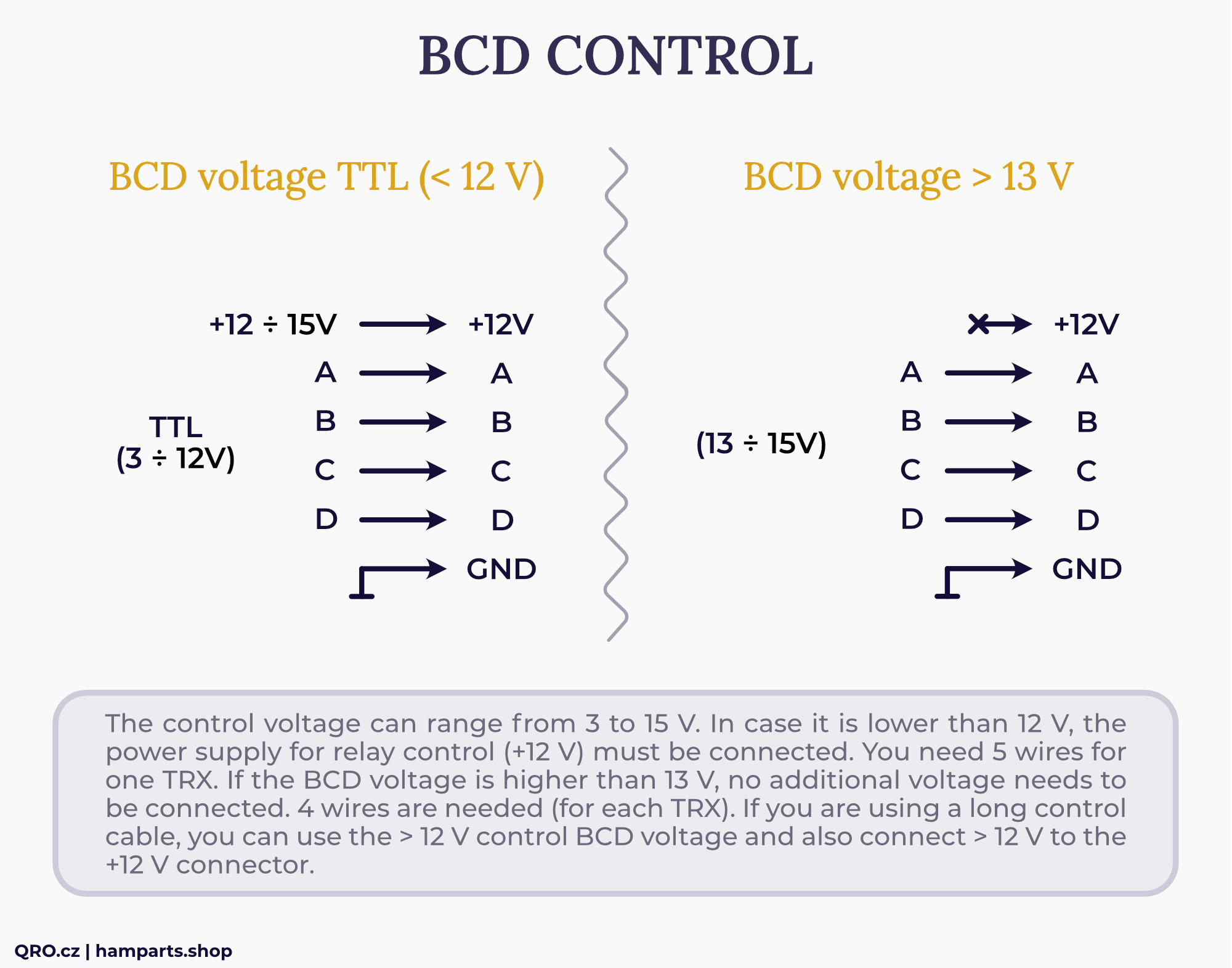
In addition to RF filters, BCD inputs contain a sophisticated circuit with optocouplers. On the one hand, it enables control over a wide voltage range with overcurrent protection, and on the other hand, it offers optical isolation.
The control voltage range for BCD inputs is typically 3 V to 15 V DC. This makes it possible to control the switch using DIY control with TTL logic. In this case, it is necessary to connect a power supply for the relay, preferably 13.8 V to the +12 connector on the BCD inputs. If you apply a control voltage greater than 13 V to the BCD, you do not need to connect an external power supply to +12. This voltage for the relay is derived from the BCD voltage.
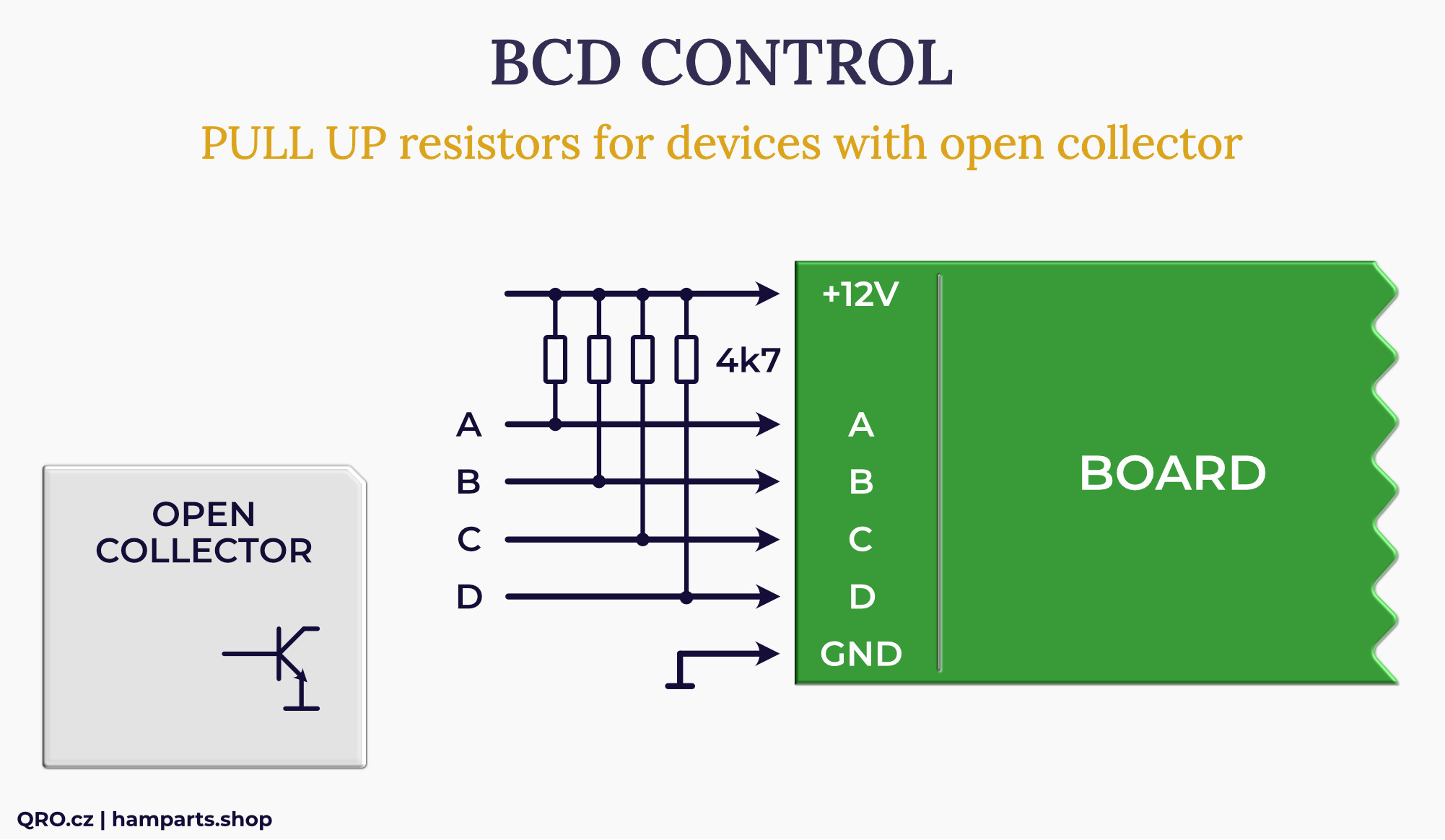
When you use device with Open Collector:
- Please check first, how big current is allowed for BCD output at device
- You have to add Pull Up resistors 4k7, 0.25 W from + 12 V DC (12-15 V)
- Or smaller 1k when you use + 5 V for Pull Ups
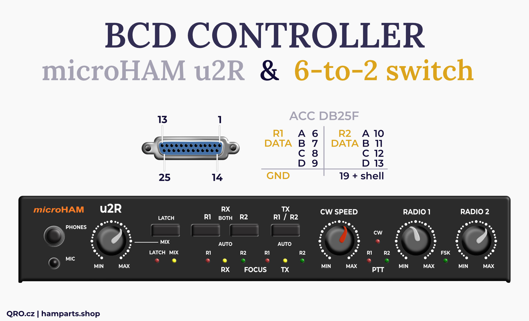
Example with Microham BCD out
LED indicatiors
The protection board contains indicator LEDs. On the sides are LEDs for BCD inputs: A, B, and C. Horizontally are LEDs indicating the connection of the given ports: 1B, 1A, 2B, etc. LEDs A4-6 and B1-3 are informative.
Fan and cooling
Since the switch is designed for indoor use, a small fan has been added. Its speed is reduced and both the cooling inlet and outlet have dust filters. If the switch is operated at low RF power (up to 500W), the fan can be disconnected. If you do not mind the slight noise from the fan, we recommend leaving it connected.
If the switch is operated in a dusty environment, we recommend regularly checking the condition of the dust filters. You can use a vacuum cleaner to clean them, for example.
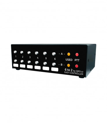
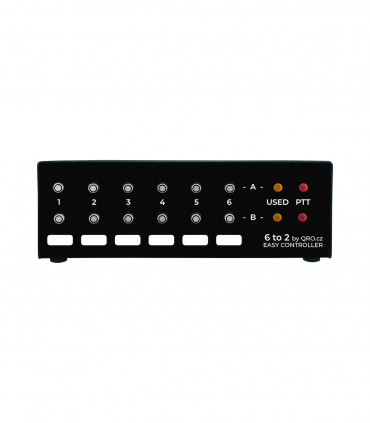
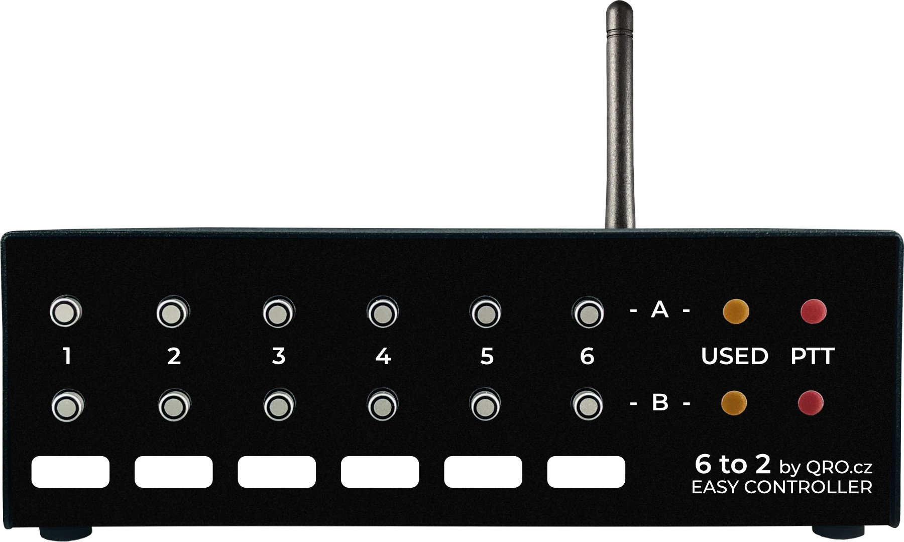
Controller example
Multiple devices can be used to control the switch. From ordinary rotary switches, through BCD outputs from PA, to our Easy Controller 6-2.
Parameters
Frequency range DC to 70 MHz
Power rating DC to 30 MHz
3 kW continue wave
4 kW PEP (SWR < 1:1.7) - tested with OM-4000
Power rating 2 kW @ 50 MHz, 1 kW @ 70 MHz
High isolation between A and B ports: 100 dB (20m), >90 dB (10m) - no port selected
High isolation A-1 and B-2: >100 dB (80m), >84 dB (20m), >80 dB (10m), 75 dB (6m), 72 dB (4m) CLASSIC
High isolation A-1 and B-6: >100 dB (80m), >84 dB (20m), >83 dB (10m), 82 dB (6m), 80 dB (4m) CLASSIC
High isolation A-1 and B-2: >95 dB (80m), >82 dB (20m), >75 dB (10m), 69 dB (6m) TRIPLEXER
High isolation A-1 and B-6: >98 dB (80m), >90 dB (20m), >83 dB (10m), 78 dB (6m) TRIPLEXER
Control DC 2 x 6 wires + 12 to 15 V or image
Control BCD + 3 to 15 V (TTL compatible or direct 13 to 15 V BCD) image
When the BCD voltage is higher than 13 V, it directly supplies the relay
BCD inputs with optocouplers and protections
BCD inputs wide range 3 to 15 V DC
BCD data format is 1 to 6
BCD inputs with positive control compatible with OM-power, Microham. Pull up for open collector - image
DC supply voltage is recommended 13.8 V
DC supply current up to 0.4 A
Fan with lower speed
Dust filters
TRIPLEXER version:
Ports 1, 3, 5 with internal dummy load 50 Ohm 5 W
Ports 2, 4, 6 connected to GND
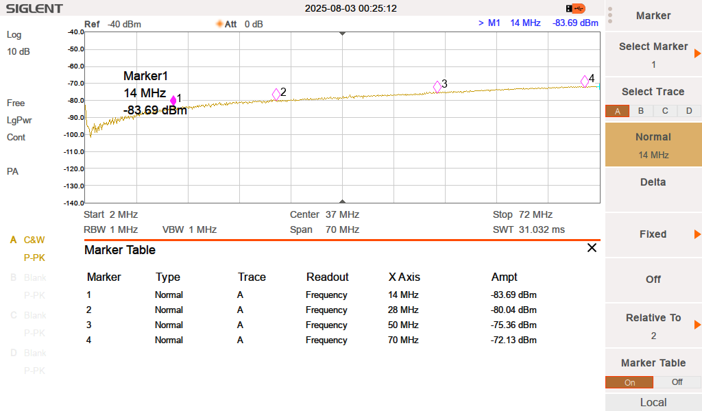
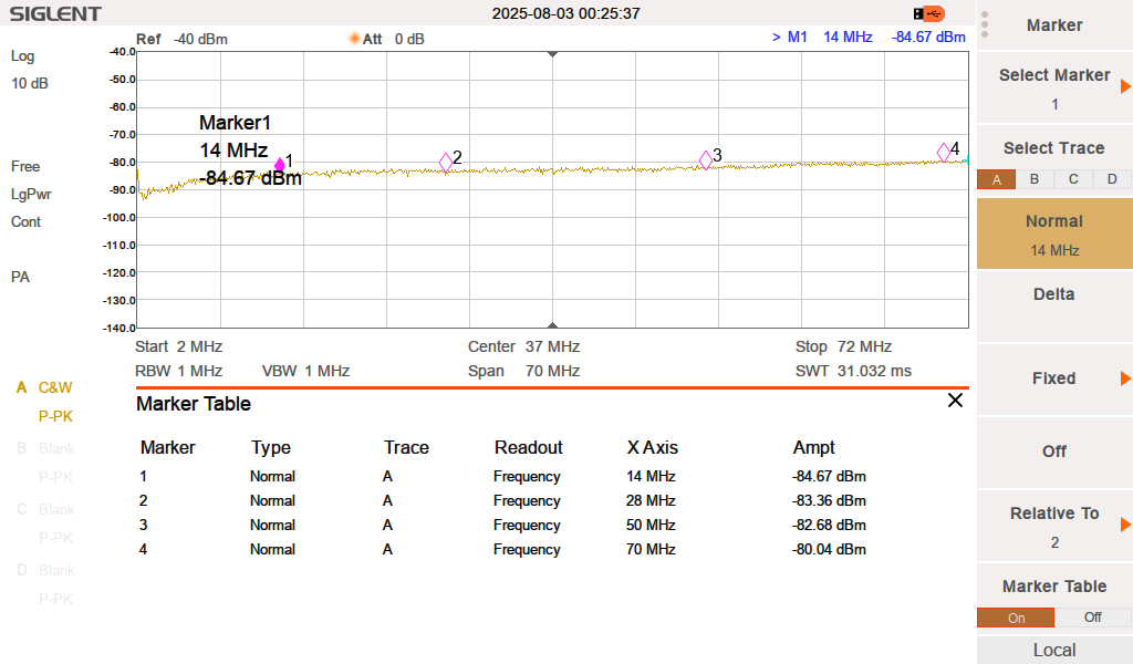
Measurements
Here are examples of RF parameter measurements for the CLASSIC version
Isolation between Ports when A goes to 1 and B to 2
Isolation between Ports when A goes to 1 and B to 6
SWR for port A1
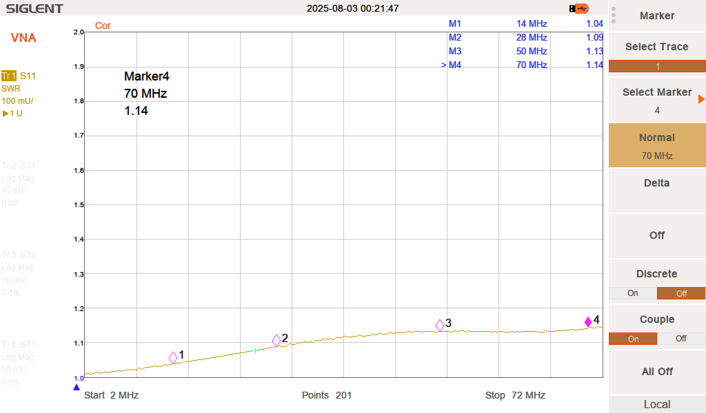
SWR for port A3

SWR for port A6
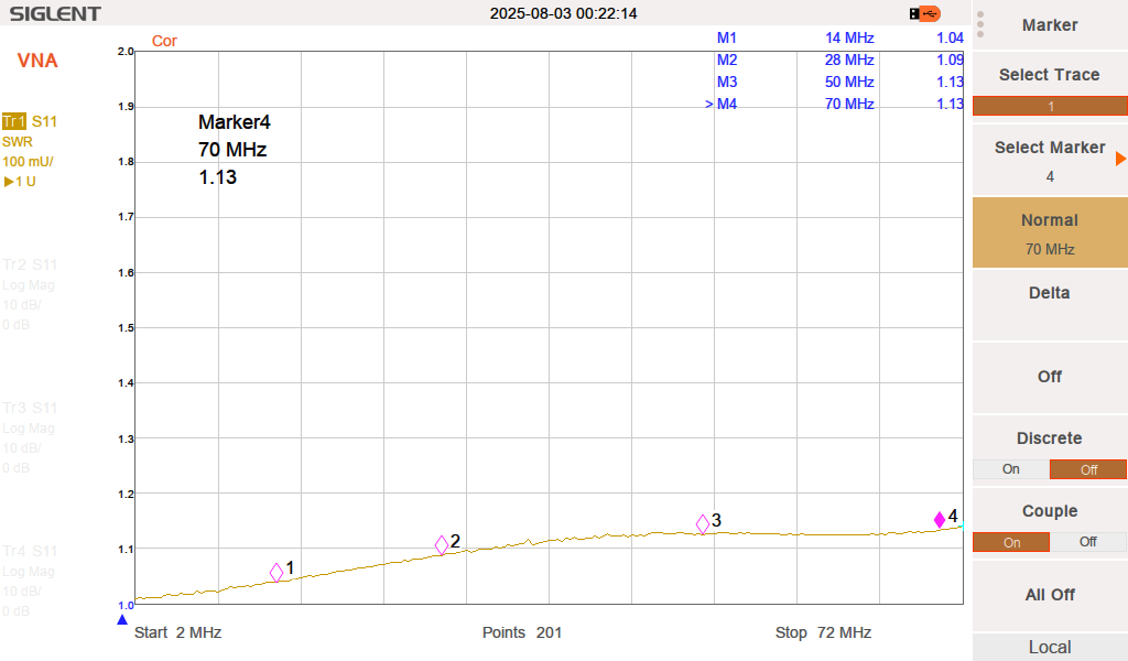
SWR for port B1

SWR for port B3
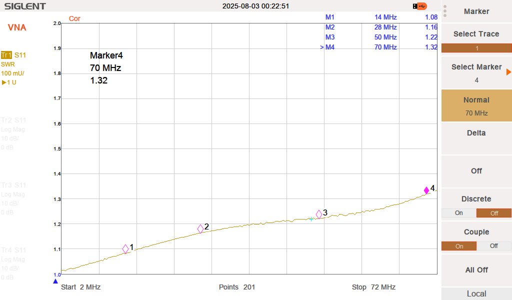
SWR for port B6

Third party software FreqEZ
ℹ FreqEZ is a Do-It-Yourself hardware/software project by Larry K8UT that provides highly configurable Band Decoding and Remote Antenna Selection. For amateurs who use N1MM+ and DXLab logging software, FreqEZ will leverage those programs TCP/UDP broadcasts for antenna switching. For other amateurs, FreqEZ can connect to the BCD band outputs available from most transceivers. The FreqEZ software and is freely available to all hams, and consists of a pair of programs that run on the Windows and Raspberry Pi Raspbian operating systems.