


330.33 €
(tax incl.)
273.00 €
(without tax)
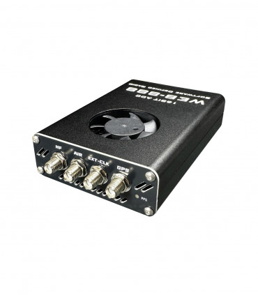
16 bit SDR receiver with LAN and lots of possibilities
select the delivery location, based on the selection, the sales prices and delivery costs will be recalculated

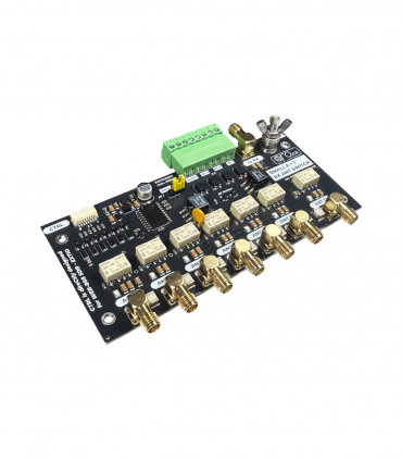
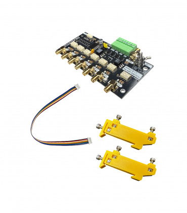
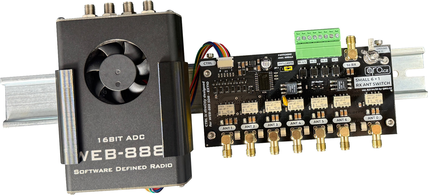
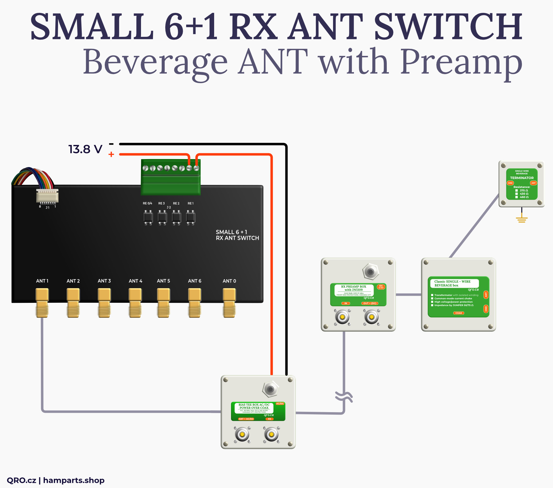
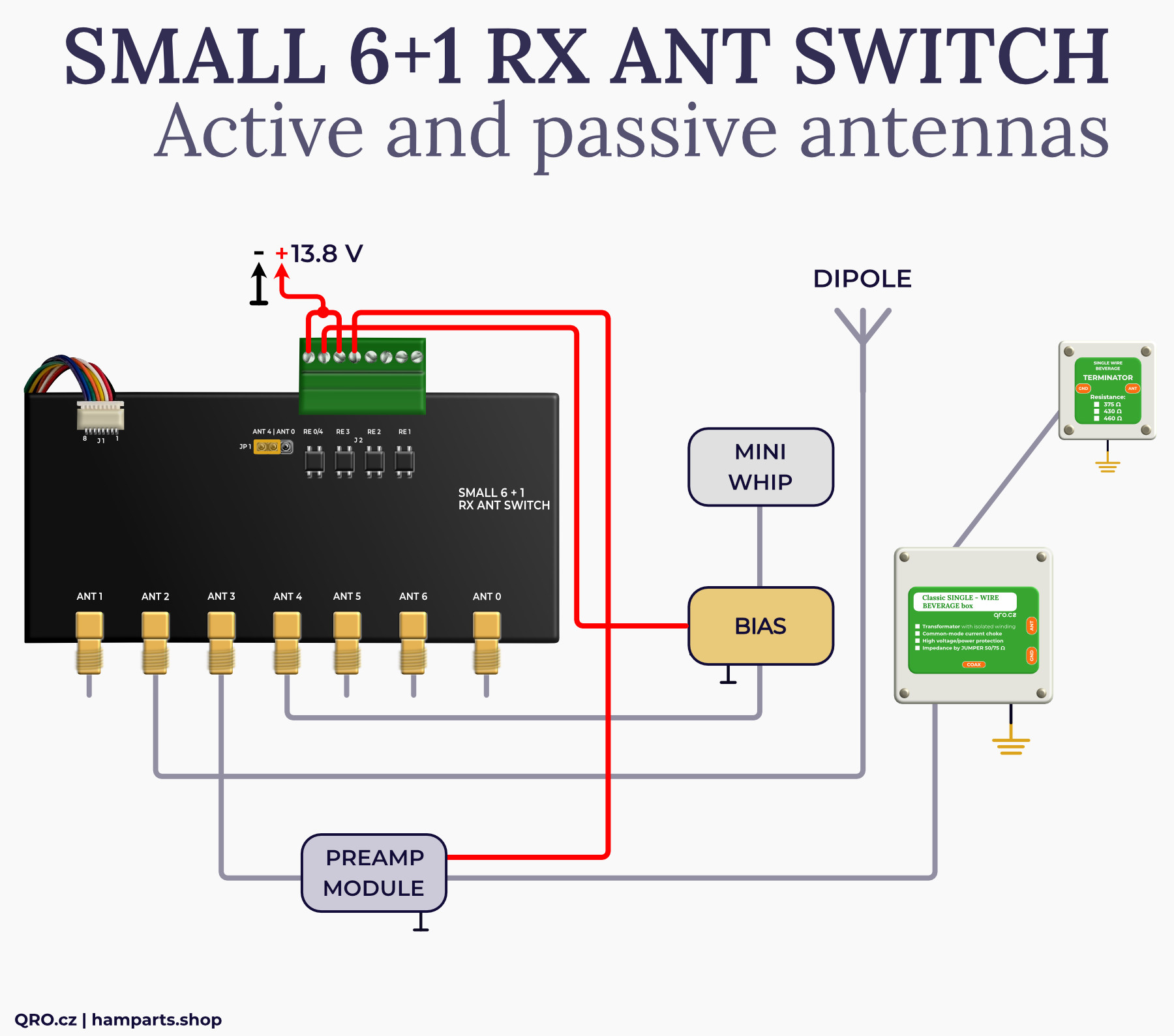
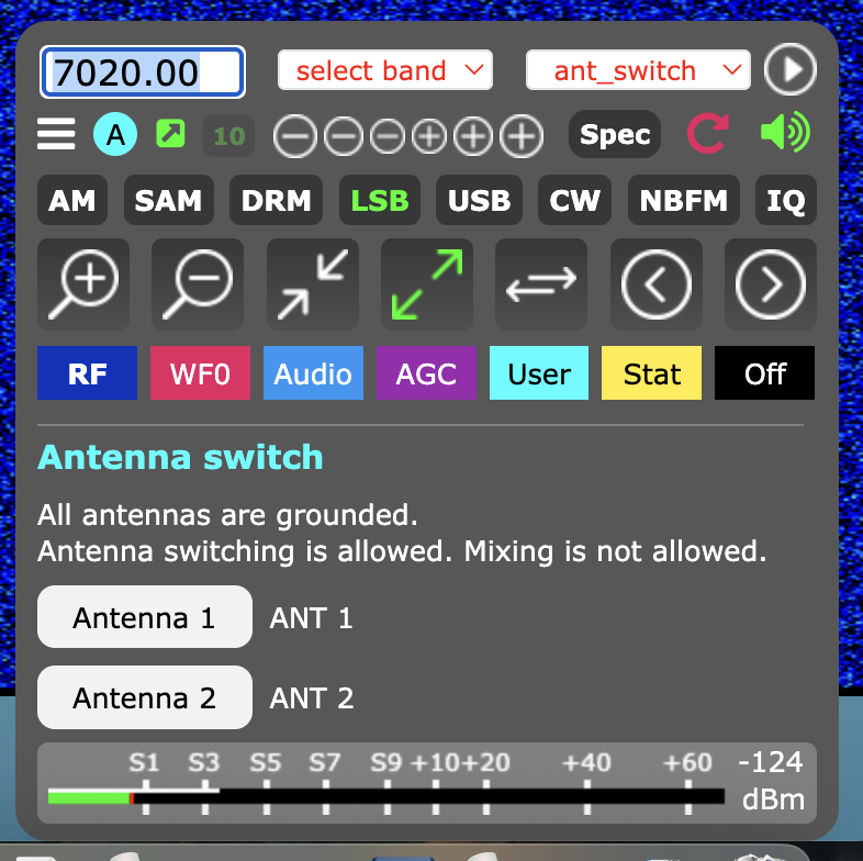
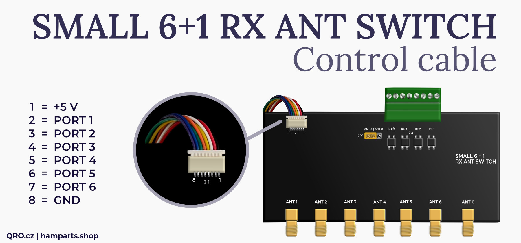
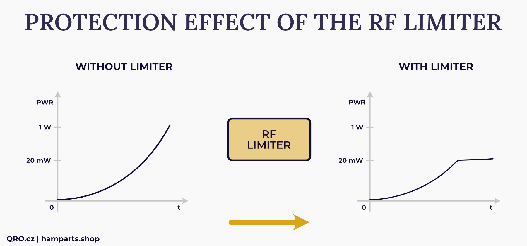
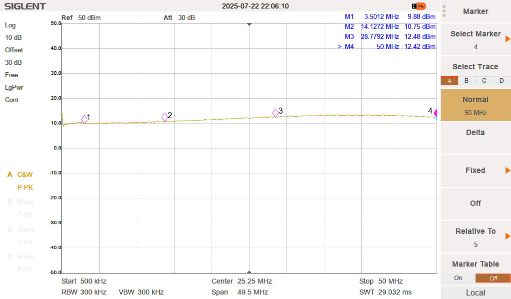
WEB-888 allows you to connect an antenna switch directly. The ability to control it directly from the web interface is very comfortable, and you can connect multiple antennas. The web interface allows you to switch up to 6 antennas. Thanks to the design of our switch, you can connect up to 7 antennas. Ports 1 to 6 are switched by external signals, port 0 is connected when no port 1 to 6 is selected or the switch is turned off. The WEB-888 has control pins connected to the GPIO of the internal FPGA. This solution can be very dangerous, and any overvoltage can damage the entire SDR. Therefore, surge protectors are additionally placed on the switch module, both on the control pins and on the antenna ports. Another unique feature is the RF limiter. It limits the output level of the RF signal to the receiver to a maximum of 10 to 12 dBm. The attached measurement shows the output level with a connected signal of 1 W (30 dBm). In addition, the serially connected SuperFuse disconnects the circuit if the input power level is very high. This fuse is reversible and protects the RF limiter. Another unique solution is the miniature SSR relays, which allow you to power external preamplifiers, additional switches, etc. These relays are active together with ports 1 to 3 and 4 or 0. More in the examples.
Applications
Parameters
Examples with antennas
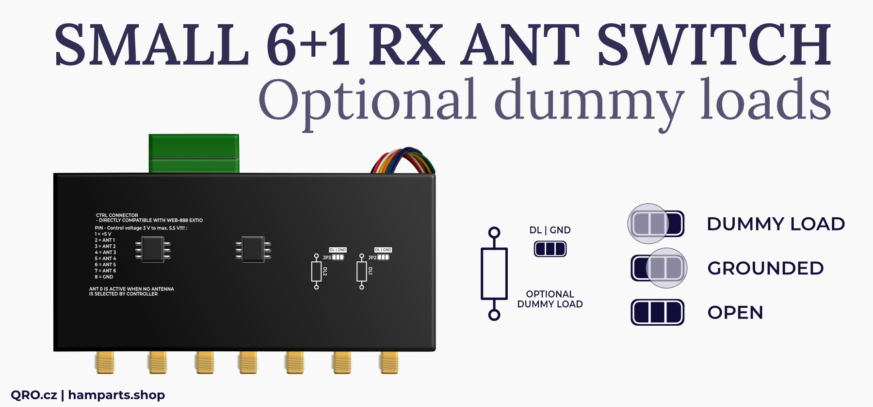
Optional dummy loads
Contacts for external devices
WEB-888 antenna switching
Connecting
RF limiter
Measurements
Grounding
Product details
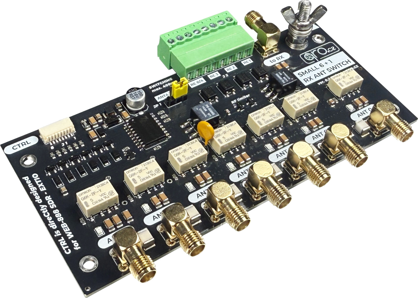
- 7 RX antenna switch
- WEB-888 antenna switch
- DIY RX antenna switch
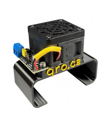
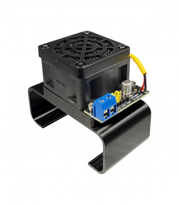
Example of mounting together with WEB-888 at DIN rail (WEB-888 holder is not included)

7 antenna inputs
Frequency range 0.1 to 60 MHz
Impedance 50 or 75 Ohm
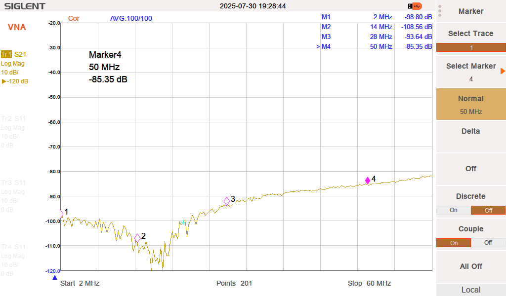
High isolation > 80 db @ 30 MHz
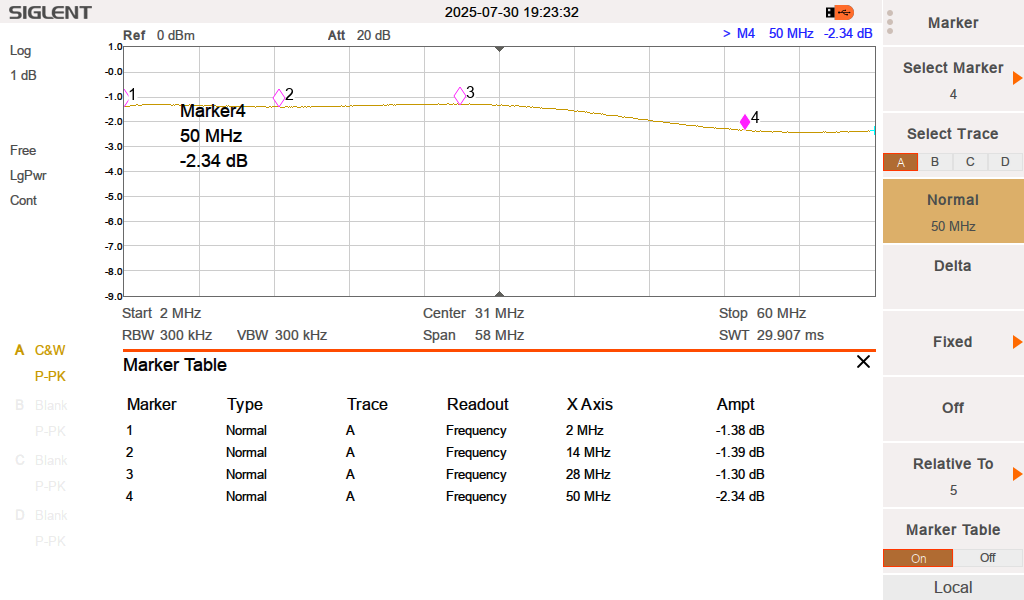
Insertion loss < 1.4 dB @ 30 MHz
Surge GDT protection 75 V
RF limiter typ. 10 to 12 dBm
Port 1 and 2 could be open, grounded or dummy load
Rest ports are grounded
When no port selected (1-6) port 0 is active
Supply voltage 5V DC
Supply current typ. 60 mA
Control voltage 3 to 5 V
Supply and CTRL voltage max. 5.5 V
Overvoltage protection at ctrl wires
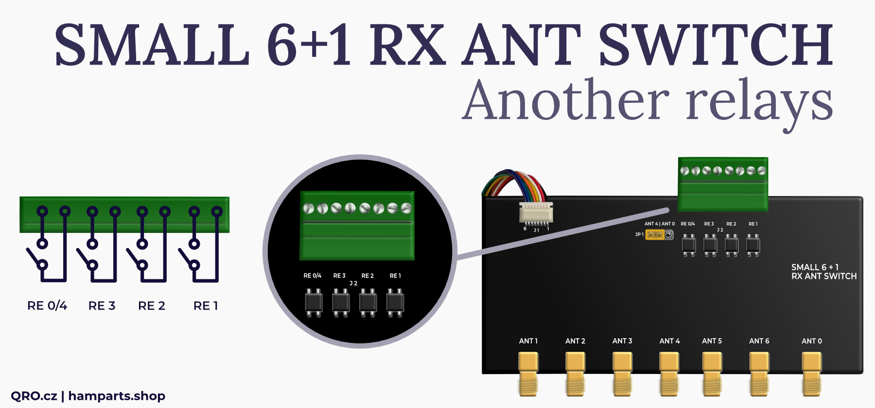
SSR contact for ports 1, 2, 3 and 4 or 0
SSR contact up to 0.4 A AC/DC
SSR open voltage max. 50 V AC/DC
LED indication
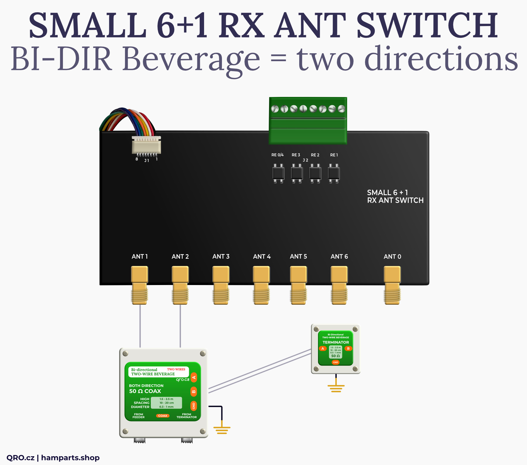
Antenna ports 1 and 2 offer small jumpers where you can select between GND and external small resistor. There you can assembly 50 or 75 Ohm resistor and use it as a dummy load when this port is not selected. This is for example with Bi-Directional Beverage antenna with 2 coax outputs. Default id grounded configuration. You can re-solder it and use knife to cut thin connection between middle and GND tap
Antenna ports 1 to 3 and 4 or 0 also switch miniature SSR relays simultaneously. These contacts allow switching AC or DC voltages up to 50V with currents up to 0.4 A. These contacts can switch, for example, the supply voltage for preamplifiers, active antennas (mini whips), or other antenna switches. The advantage is that the preamplifier or active antenna will only be active only if the selected antenna port is chosen.
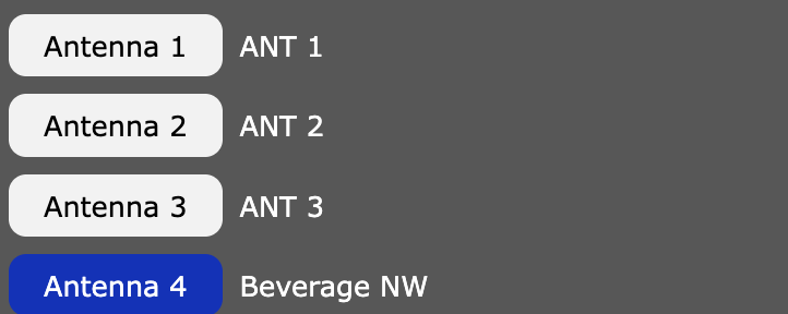
WEB-888 has an EXTIO connector on the front panel where you can connect an external antenna switch. Thanks to the FW authors, you can conveniently switch antennas from the web interface. You can choose 1 of 6 or mix antennas.
⚠ WARNING: The EXTIO connector leads directly to the FPGA GPIO pins. There is no protection and they are only compatible with 3V3 logic. Overvoltage on these pins can irreversibly damage the FPGA. Our switch includes additional protection.
You can find our technical articles. You can download last firmware at rx-888.com.
If you have the correct firmware version, log in to administration (http://ip.address/admin).
In the Extensions tab, you will find Antenna Switch:
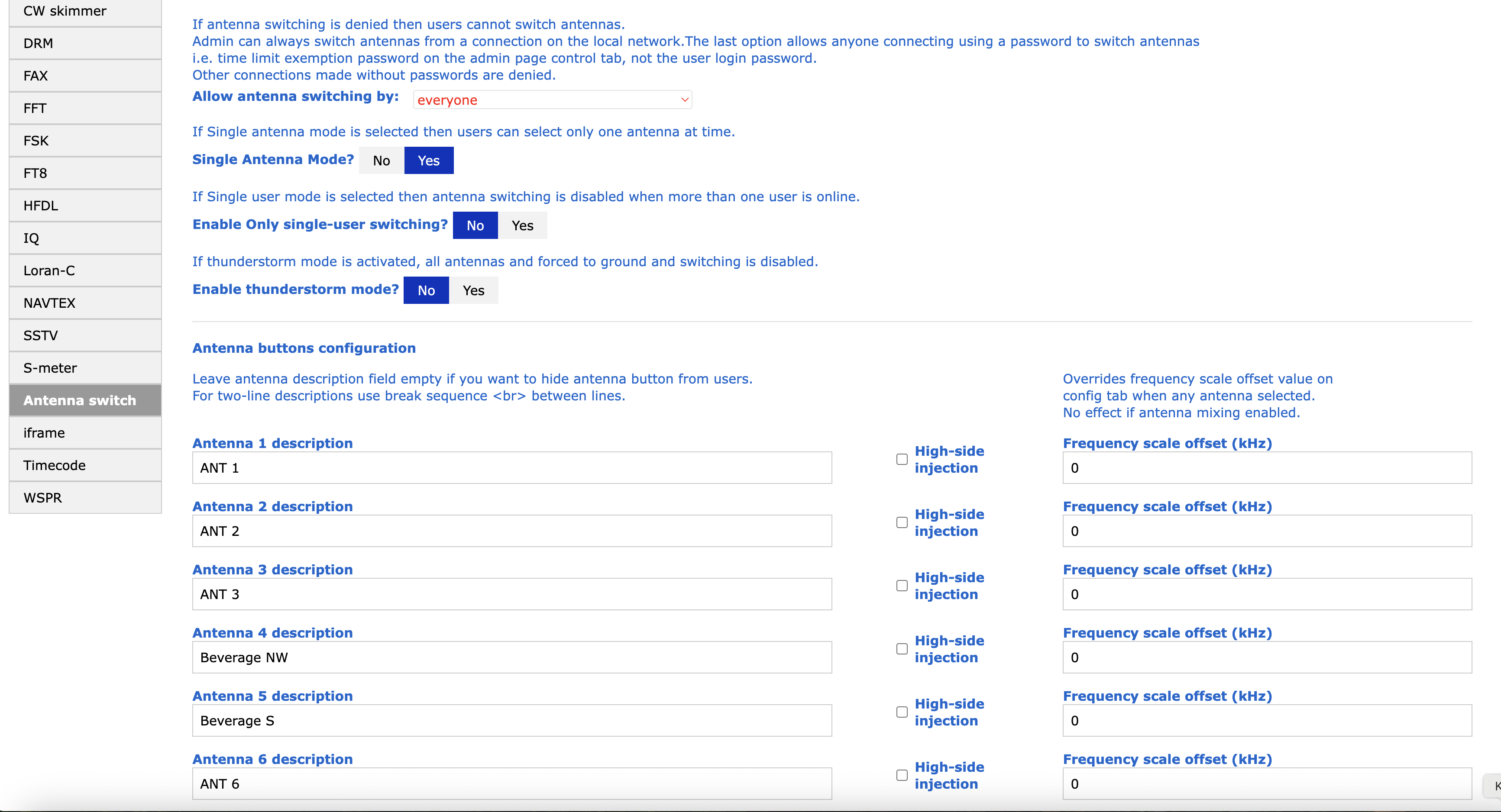
There you can enable Single Mode - it means you can select only one antenna (switch 1 of 6). Add names to the antenna ports - you will see it later in web interface. When there is no name fot the antenna port, it will stay disabled.
Although the with is designed for direct connection with WEB-888, you can also control it in other ways:The RF limiter offers additional and very important protection. Many SDR receivers only have a transformer at the input, and the signal then continues directly to the ADC converter. If a strong signal is fed into the input, it can easily cause irreversible damage to the ADC converter. Inserting an RF limiter into the path limits the maximum RF signal level. Thanks to its unique design with transformers, fast diodes, and SuperFuse, this RF limiter has no effect on IMD. Limitation occurs at a level where the ADC converter itself is at the threshold of overload.
- other IP/USB relays
- rotary switch
- buttons, etc.
The switch requires a supply voltage of 5 V DC. The control inputs are controlled by a HIGH logic level. The control voltage must be between 3 and 5 V.
Internal protection prohibits the use of voltage higher than 5.5 V for both power supply and control.
The RF limiter offers additional and very important protection. Many SDR receivers only have a transformer at the input, and the signal then continues directly to the ADC converter. If a strong signal is fed into the input, it can easily cause irreversible damage to the ADC converter. Inserting an RF limiter into the path limits the maximum RF signal level. Thanks to its unique design with transformers, fast diodes, and SuperFuse, this RF limiter has no effect on IMD. Limitation occurs at a level where the ADC converter itself is at the threshold of overload.
Here is an image of the RF limiter function and an example of a measurement where a signal with a power of 1 W (30 dBm) is fed to the switch input and the measurement is taken at the receiver output (in range 500 kHz to 50 MHz).
Insetion loss for port 0
Isolation port 0 to open when different port is selected
The device includes several protections. Connecting antennas may cause overvoltage during storms. We recommend using multiple levels of protection and ensuring good grounding from the antenna. The switch also includes GDT (Gas Discharge Tubes) surge protectors, which dissipate voltages higher than 75 V. However, the path of the surge voltage is very important. It is necessary to connect a sufficiently thick and short conductor from the GROUND ME !!! screw to a good ground in the hamshack.
If you do not make this connection, overvoltage may be conducted through the SDR, its power supply, or the LAN cable. This can damage multiple devices! Similarly, switching USB power supplies can produce AC voltage between the negative pole of the DC output and the protective conductor (GND).
Therefore, please pay close attention to the connection of the grounding conductor!
Product details
Switch board assembled and tested
Flat cable for WEB-888
DIN rail mounting KIT
| Bord dimensions (mm) | 125x77x27 with connectors (without DIN rail mounting KIT) |
|---|---|
| Weight brutto (kg) | 0.155 kg |
Ing. Jan Šustr
ID 05476356, VAT CZ8407024780
Palachova 1777/7, 591 01 Žďár nad Sázavou, Czech republic, Europe
Please also read general instructions before handling the product.
ID 05476356, VAT CZ8407024780
Palachova 1777/7, 591 01 Žďár nad Sázavou, Czech republic, Europe
is compatible with the relevant Union harmonisation legislation directives:
EMC Directive 2014/30/EU
ČSN EN 61000-6-3 ed. 2
ČSN EN 61000-6-1 ed. 2 (333432)
On behalf of Ing. Jan Šustr (QRO.cz)
Ing. Jan Šustr, CEO
5th August 2025
Please sign in first.
Sign inCreate a free account to save loved items.
Sign inCreate a free account to use wishlists.
Sign in