
12.10 €
(tax incl.)
10.00 €
(without tax)
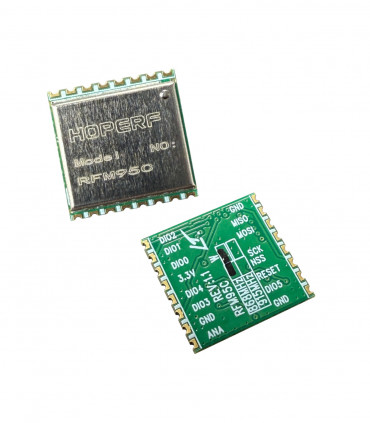
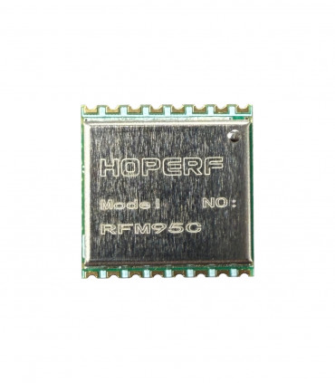
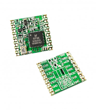
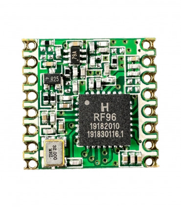
This is small RF transceiver module with LoRa modulation.
select the delivery location, based on the selection, the sales prices and delivery costs will be recalculated

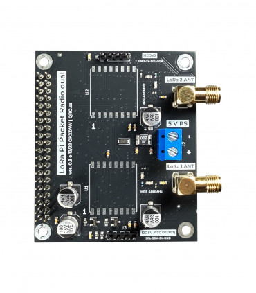
This is a specially designed daughter board for Raspberry PI with the possibility of direct 5V power supply. The board can be used for experiments with LoRa APRS, LoRa Packet Radio, Meshtastic , Meshcom and others. I2C connectors with 5V and 3.3V logic and two positions for RFM9x LoRa modules. LoRa modules include 400MHz High Pass Filters on the antenna inputs. This allows LoRa radios to operate at 400MHz and above. The filter limits signals from 2m APRS transmitters. The I2C ports can be used for OLED displays as well as, for example, for a real-time RTC circuit.
Applications
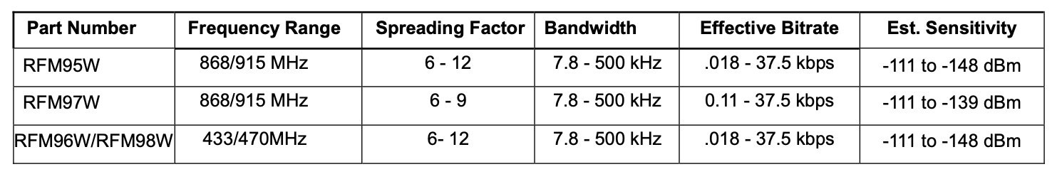
Technical parameters
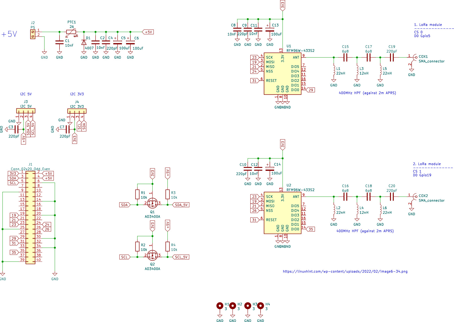
Schematic
GPIO configuration
Connectors
Example
Product details
Raspberry PI daughter board for projects involving LoRa modules. The original use was in the LoRa APRS network. This was followed by experiments with LoRa Packet Radio - a recreation of Packet Radio, but using LoRa radios for data transmission. You can of course use this board for other projects like Meshtastic, Meshcom or LoRa scanners etc. Just set up the GPIO and the module you are using correctly.
Useful links:
LoRa APRS Gateway: iot4pi.com
LoRa APRS Facebook: facebook.com
Meshtastic (not tested): meshtastic.org
LoRa Packet Radio: ok2zaw.blogspot.com
LoRa Packet Radio Facebook: facebook.com
LoRa python-based KISS TNC: github.com
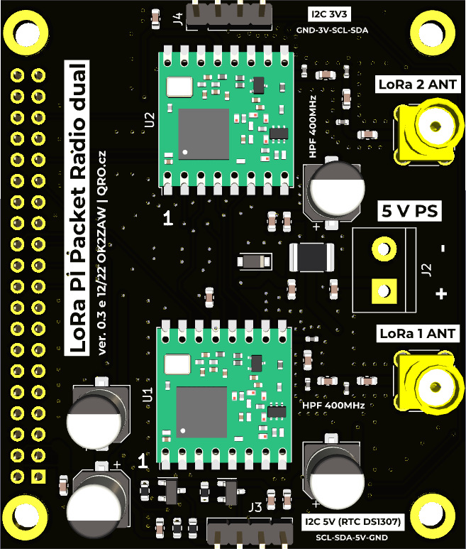
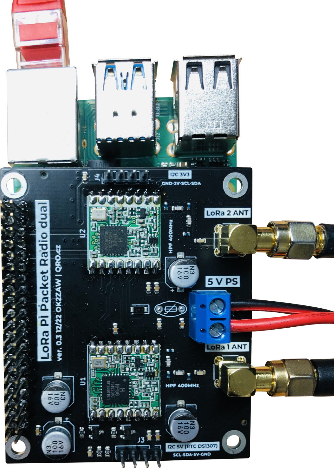
Daughter board PCB
Raspberry PI 4, 5, zero compatible
Direct 5V up to 2A supply
Positions for two RFM9x LoRa modules
HPF 400MHz at antenna ports
SMA RF ports
I2C 3.3V and 5V
Long Pin header for sandwich boards
There is schematic diagram. You can see it in PDF.
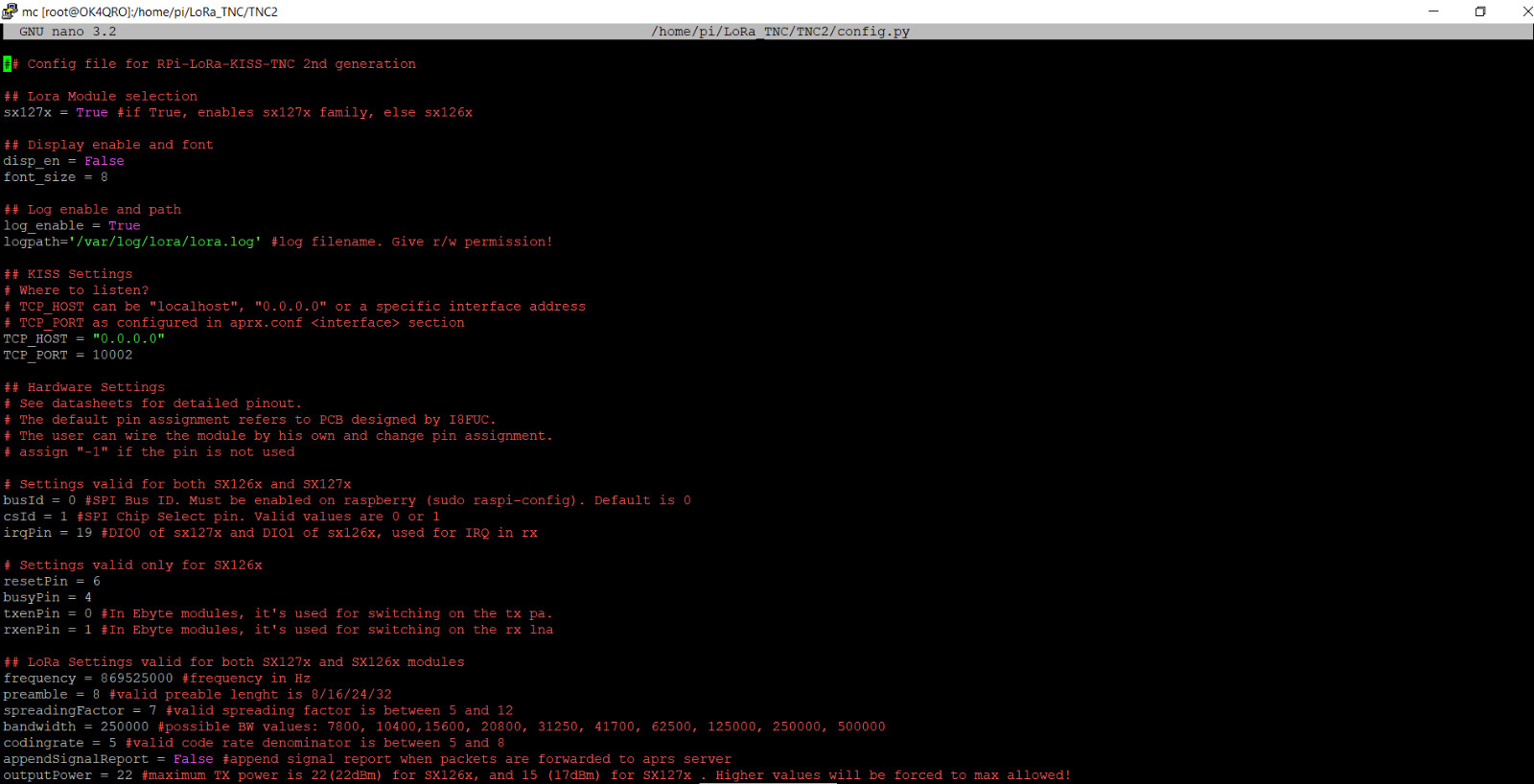
You have to set right GPIO pin numbers in the Raspberry PI software. Remember, there must be RFM9x modules. You can use these one, which are pin compatible:
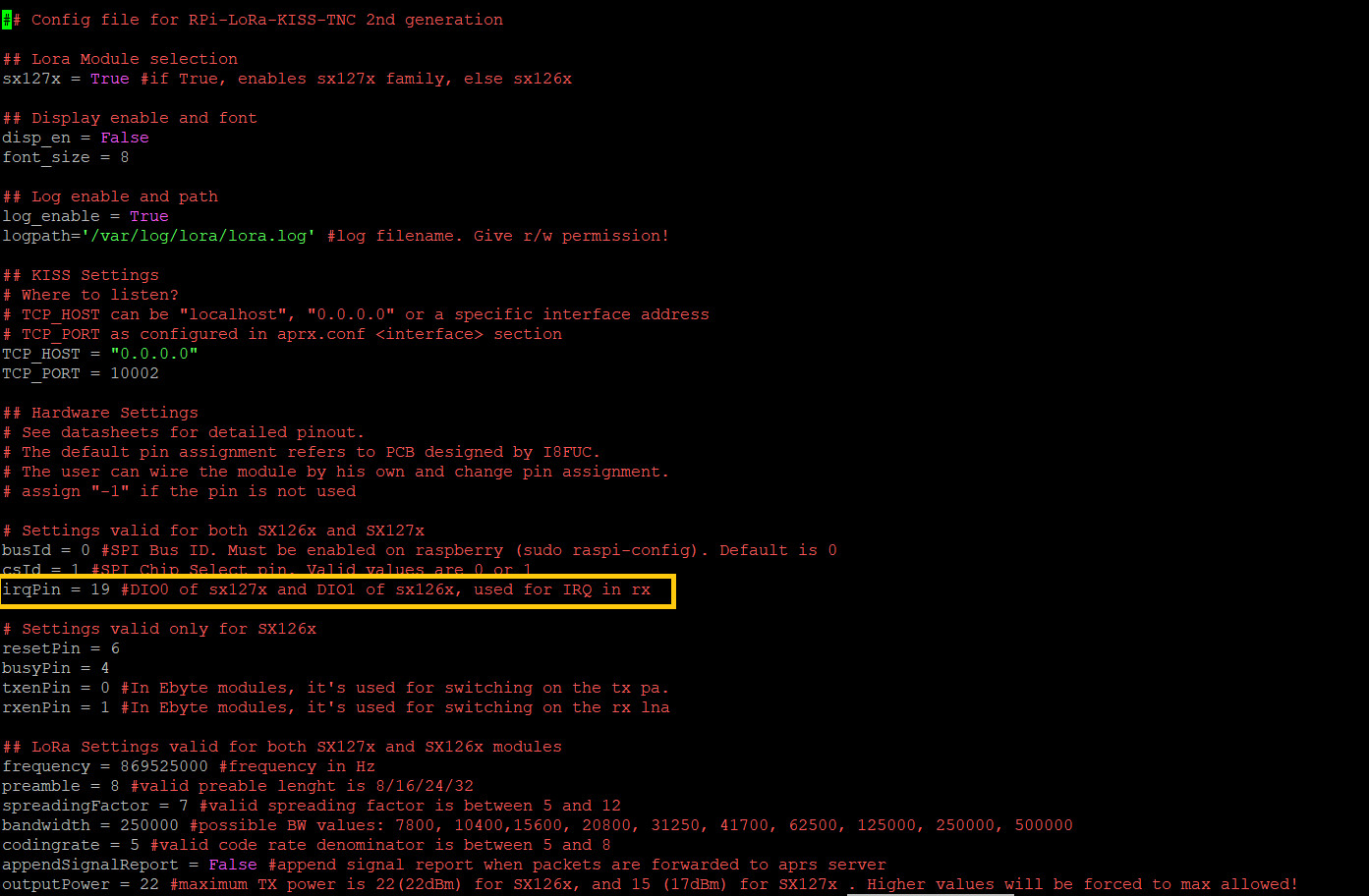
GPIO setup:
LoRa module 1: CS = 0, D0 = GPIO5
LoRa module 2: CS = 1, D0 = GPIO19
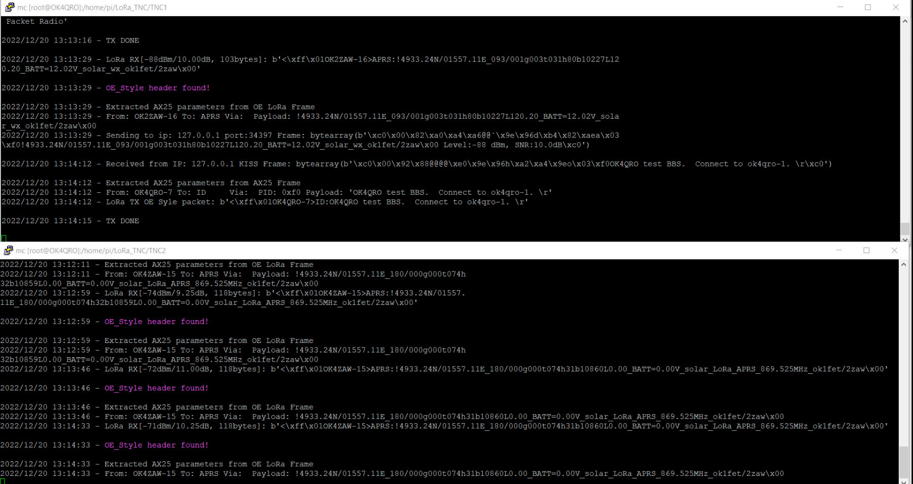
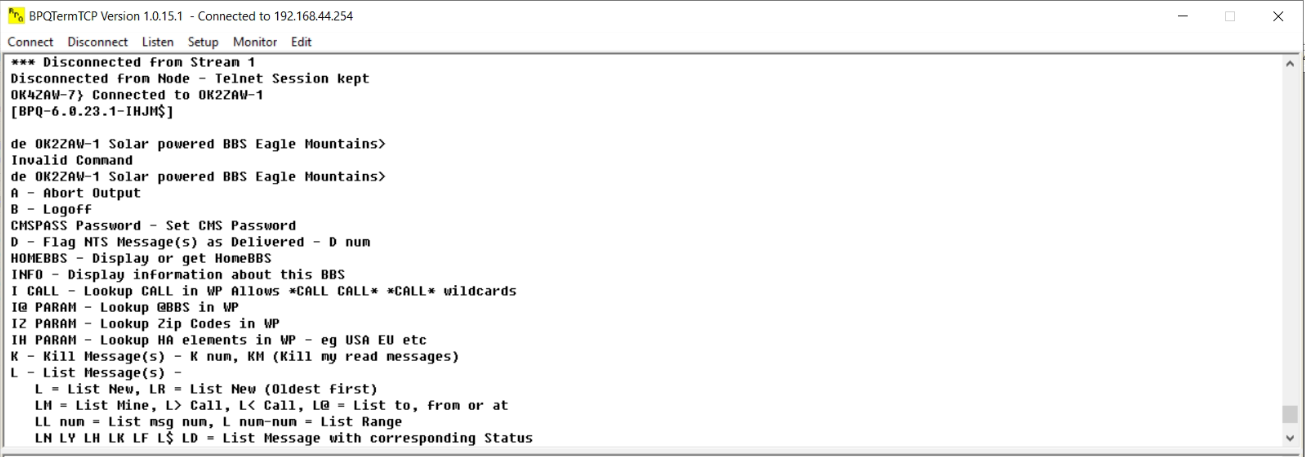
Example for LoRa Packet Radio TNC:
There is a few connectors. Main 40 pins is for Raspberry PI GPIO. There is female socket to Raspberry and long pin headers for possible another daughter board.
- is 5V DC in, max. 5V with PTC fuse
- you can supply daughter board as well as Raspberry board
- NO extra power supply needed
- there are two I2C connectors
- one should be 5V and second 3.3V logic for external parts like OLED, RTC etc.
- SMA RF connector for LoRa module U1
- SMA RF connector for LoRa module U2
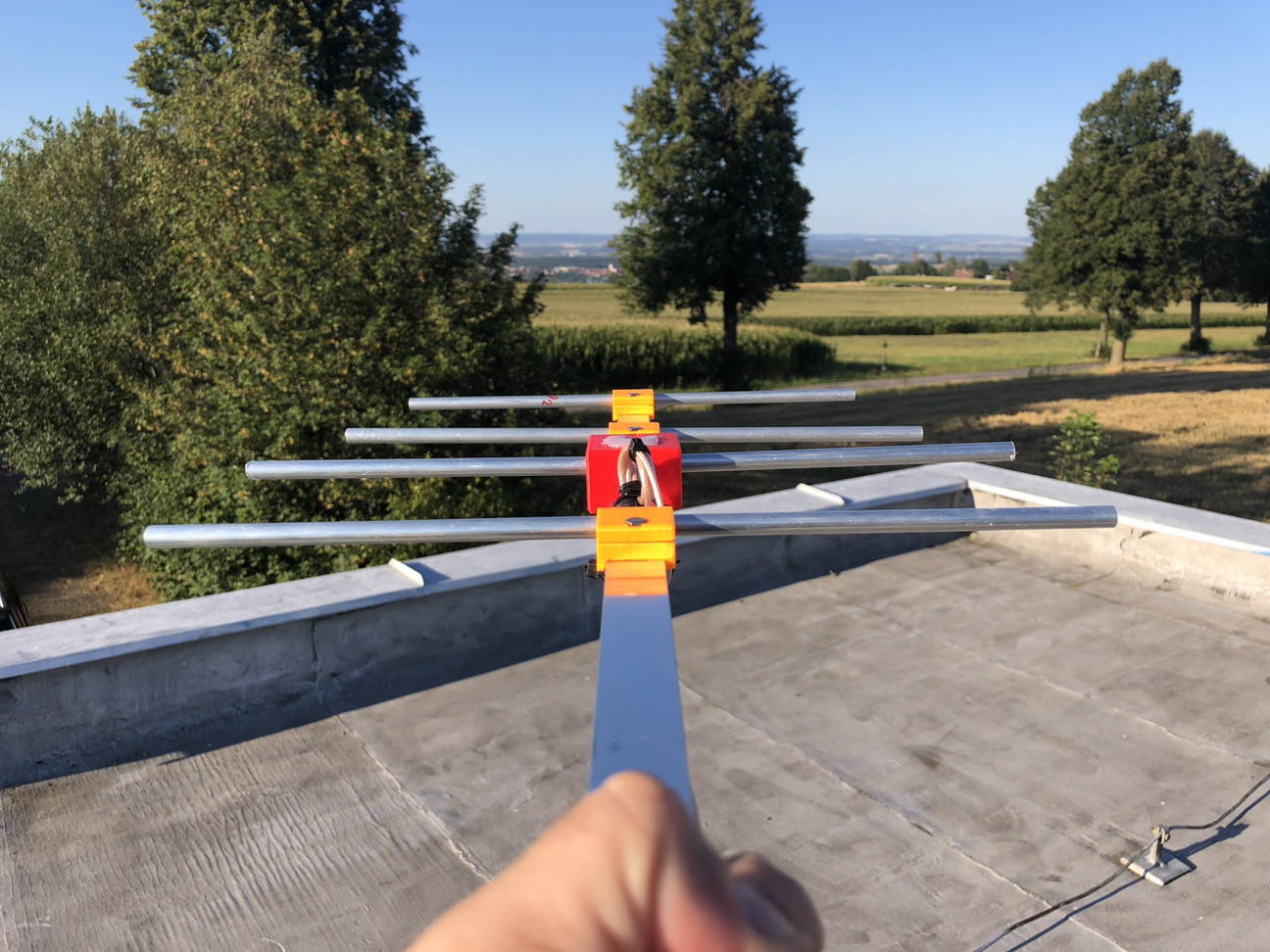
There are examples of use as LoRa Packet Radio. On eis solar powered in Eaglo Mountains with two LoRa TRX. On efor 433MHz and second for 868MHz.
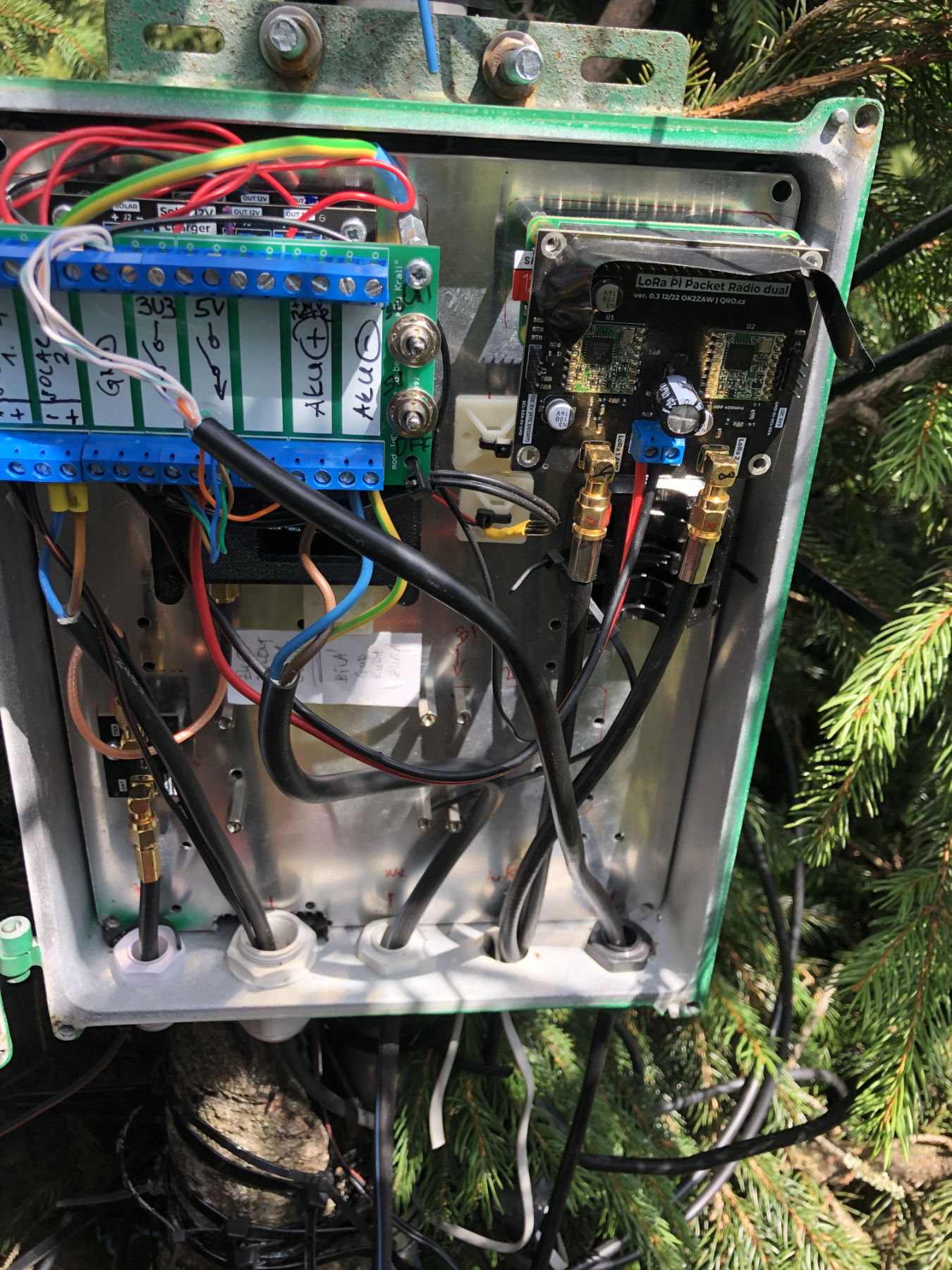
Second is close to my city, with two radios as well:
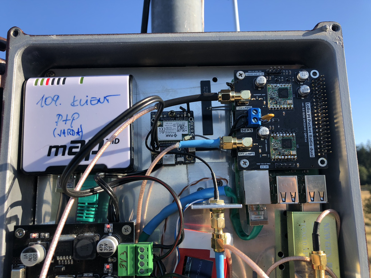
There is example with OLED and RTC module on Packet Radio TNC setup:
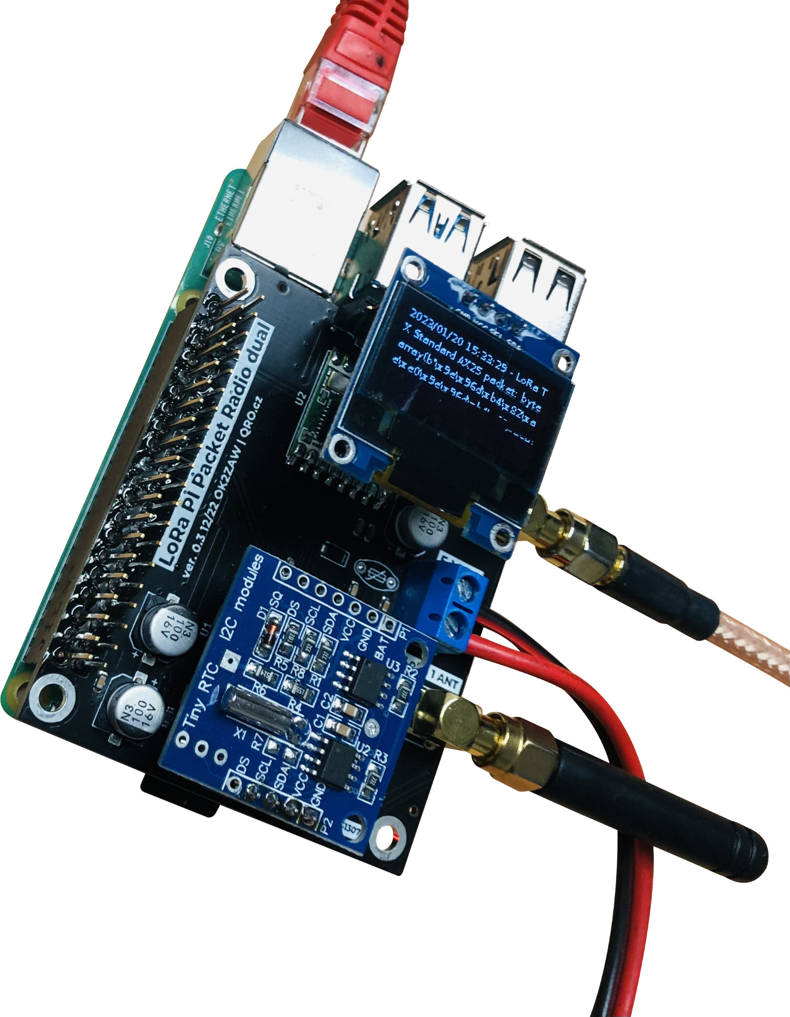
You can find more about installation and configuration at my blog: ok2zaw.blogspot.com. There are SD card images and also example with RTL-SDR 2m APRS over the LoRa peer.
Easy communication at 100km without direct visibility at v433 MHz with 30mW:
Product details
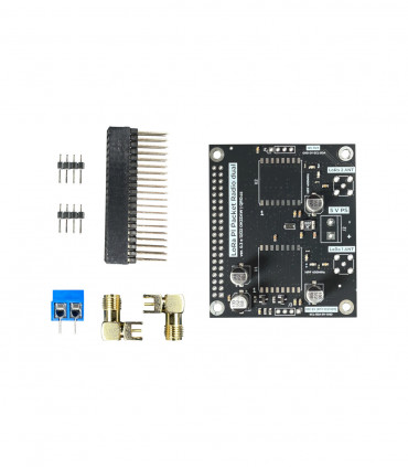
KIT contains:
PCB board with all SMD parts assembled
SMA connectors
PIN headers (long and short)
WAGO connector
| Weight brutto (kg) | 0.058 kg |
|---|
Ing. Jan Šustr
ID 05476356, VAT CZ8407024780
Palachova 1777/7, 591 01 Žďár nad Sázavou, Czech republic, Europe
Please also read general instructions before handling the product.
ID 05476356, VAT CZ8407024780
Palachova 1777/7, 591 01 Žďár nad Sázavou, Czech republic, Europe
is compatible with the relevant Union harmonisation legislation directives:
EMC Directive 2014/30/EU
ČSN EN 61000-6-3 ed. 2
ČSN EN 61000-6-1 ed. 2 (333432)
On behalf of Ing. Jan Šustr (QRO.cz)
Ing. Jan Šustr, CEO
29th January 2025
Please sign in first.
Sign inCreate a free account to save loved items.
Sign inCreate a free account to use wishlists.
Sign in